

description
o-ring most widely use as sealing element. o-rings offer to the designers an ef- ficient and economically advantageous sealing element for a wide range of various static and/or dynamic applications. cost-effective way of production and easy us- ability made from the o-rings the most expanded sealing element. the wide range of elastomer materials for standard and special applications enables usage of the o-rings for sealing of practically all liquid and gaseous media.
the o-rings are vulcanised in dies and are characterised by their ring shape with round cross-section. the size of the o-ring is defined by internal diameter Ød and by cross- section H (thickness). please see picture below.
the cross-sections from 0.35 to 15 mm and the internal diameters up to 5,000 mm are available.
function
the o-ring is a double-acting sealing element. the sealing effect is achieved by deformation of the round profile of the o-ring. the size of the deformation is determined by the groove depth t. the deformation, which is sometimes called also depression or pre-tension, acts in radial or axial direction and provides the o-ring with the initial sealing ability. under pressure, the o-ring behaves similarly as a liquid with high surface tension. the pressure is uniformly transferred in all directions. the force raised by the initial deformation of the o-ring is added to the force raised by the pressure in the system and they together create the resulting sealing force.
advantages
compared with other sealing elements the o-ring features many advantages:
– it inexpensive and enables cost-effective solutions;
– it may be used as the single and double acting solutions due to its symmetrical diameter;
– simple groove decreases costs for design and production;
– compact shape enables lower built-up;
– simple and reliable installation, incorrect assembly is not possible;
usability area
- usability for wide range of static and dynamic sealing applications;
- wide choice of mixtures for compatibility with most of the liquids
- the o-rings are used primary as the sealing elements and as activating elements for combined sealants and oil scraper rings.
- the o-rings are mostly used as the static seal
- with radial compression, e.g. for cocks, valves, hydraulic cylinders etc.
- with axial compression, e.g. flange joints, lids, hydraulic elements etc.
- for dynamic applications, the o-rings are recommended only for mild operating conditions. their life-time depends above all on existenceof the lubricating film, system pressure, temperature, size of the sealing gap, speed/type of media, and on the surface quality of areas of
the metal components.
very generally it is possible to recommend the limit values of 100 bar or 0.3 m/s, respectively the product p x v ≤ 2 [MPa, m/s].
in case the larger gaps are needed, it is always necessary to use the back-up ring according to the pressure application from one / both
ends of the o-ring. for rotational movement, the o-rings are generally not suitable, as the lubricant supply to the sealing surfaces is imper-
fect. during the movement, increase friction an occur, local overheating and quicker wearing.
if exceptionally other sealing element may not be used, it is more suitable to assemble the o-ring on the stationary part. then the centrifu-
gal force does not affect on the o-ring. more suitable types of the sealants are available for most of the rotation applications.
overview of materials
polyacrylate rubber (ACM)
the excellent characteristic of the acrylate rubber is its excellent resistance against high temperatures and hot oil. ACM is resistant against engine oils with modern additives, gearbox oils, lubricating greases etc. besides this, it features the high oxidation and ozone resistance of the saturated polymer chain. the temperature range is from –40 °C to +200 °C.
acrylonitrile-butadiene rubber (Nitrile rubber) (NBR)
the NBR rubber is resistant above all against effecting of oils, mainly hydraulic oils, lubricating oils, petrol and other aliphatic hydrocarbons, acids and bases. good physical properties such as high durability, abrasion resistance and temperature resistance (-25 °C – +125 °C) ensure to this type of rubber wide area of usage.
hydrogenated acrylonitrile-butadiene rubber (HNBR)
the sealants from the HNBR rubber feature excellent spectrum of characteristics. the high resistance against additive technical oils, low liquid
/ gas permeability, good flexibility at coolness to –40 °C, good resistance against ozone and high abrasion resistance. the HNBR are resistant
against temperature up to +145 °C.
chloroprene rubber (CR)
chemical and physical characteristics of the CR rubber are similar to the ones of the NBR rubber. however, the resistance against mineral oils is somewhat lower, but the resistance against the ageing, ozone, acids and alkalis are excellent. the application temperature range is from –40 °C to +120 °C.
butyl rubber(IIR)
sealants from the material feature very low permeability of gasses, high resistance against oxide and ozone, good electric properties and excel- lent resistance against animal and vegetable oils/greases. this material is not suitable for applications with mineral oils. the application tempera- ture range is from –40 °C to +140 °C.
natural rubber (NR)
the natural rubber is highly elastic material with excellent physical properties. in spite of wide range of synthetic rubbers with special character- istics, the natural rubber is still extensively used. the temperature range is from –45 °C to +100 °C.
chlorsulphonated polyethylene rubber (CSM)
CSM features excellent resistance against ozone, acids and alkalis, is resistant against ageing, and has good mechanical and physical proper- ties. the mineral oils may cause the swelling, whose size depends on the application temperature and type of hydrocarbons components. the temperature range is from –25 °C to +135 °C.
ehtylene propylene diene rubber (EPDM)
the usage area of the rubber is in case, where the high resistance against hot water and steam is required from the used sealant. besides this, the EPDM is very resistant against ageing and ozone. the resistance against freezing may be treated as good compared with usual types of synthetic rubbers. the behaviour under influence of oils, lubricating greases and solvents approximately corresponds to the properties of the butadiensty- rene rubber (SBR). the resistance against chemicals, even oxidizing, is very good. the temperature range is from –40 °C to +140 °C.
fluorocarbon rubber – viton® (FPM, FKM)
extraordinary resistance against mineral oils, aliphatic and aromatic hydrocarbons and chlorinated hydrocarbons, concentrated and rarefied ac- ids and mild alkali substances. the excellent temperature resistance up to +200 °C and resistance against low temperatures to – 30 °C according to used types, high mechanical values and excellent resistance against ageing classify the FPM rubber high above usual synthetic rubbers.
fluorocarbon rubber viton ® extreme™
excellent resistance of the fluoroelastomer against the chemicals is yet superseded by the viton® extreme™ material. the modified polymer struc- ture significantly decreases the swelling in solvents and high alkali medias, the resistance against temperatures and flexibility under low tem- peratures are preserved and range from –15 °C to +200 °C. this material is used in areas, where the aggressive chemicals require high resistance.
polytetrafluoroethylene teflon® (PTFE)
beside general resistance, it features the resistance against alkali metals and gaseous fluorine under pressure. good sliding characteristics, low wearing, heat resistance from –200 °C to +260 °C. regarding the PTFE hardness of cca 95° Dhore, the assembly into open grooves is recommend- ed.
tetrafluoroethylenepropylene rubber (TFE/P) aflas®
aflas is a special rubber and belongs to the newer generation of fluoroelastomers. the sealing rings from aflas feature extraordinary resistance against whole range of specific medias and chemicals, such as hot water, water steam, acids, alkalis, ammoniac, bleaching agents, sulphur gases and oils and amines, especially against medias with additives, containing amines and corrosion inhibitors, additive engine and gearbox oils, break liquid and medias with oxidants. the application temperatures are similarly as for fluoroelastomers from –20 °C to +200 °C. mostability from – 200 °C bis +260 °C. Regarding hardness PTFE c. 95° shore advises assembly bis open grooves.
fluorsilicone rubber (FVMQ)
the fluorsilicon rubber features besides typical properties of normal silicon rubber also the substantially improved resistance against the oils, fuels and solvents. this characteristic applies above all for aromatic and chlorinated hydrocarbons and alcohols. the application ranges are therefore determined above all for requirement for resistance at the wide temperature range from –60 °C to +200 °C by simultaneous affecting of aggressive medias as e.g. petrol, alcohol mixtures, aromatic oils and number of chlorinated solvents.
silicon rubber (VMQ)
the application area of the rubber is based on its excellent heat resistance (-55 °C to +200 °C), however it cannot be transmitted to hot water or steam. even if the silicon rubber resistance against oils is approximately at the level of NBR, the good physically mechanical properties of the material are not achieved.
polyurethane rubber (AU)
the sealants from the polyurethane rubber feature above all high resistance. the sealing rings from polyurethane feature high mechanical values, such as breaking / abrasion resistance, high reflection elasticity and good properties for sealing of gases. the resistance against fuels and against number of technically usual oils, mainly against the oils with high content of aromatics, is excellent. the sealants from the polyurethane rubber have with regard to good heat resistance (up to +125 °C) and good flexibility under low temperatures (to –30 °C) also the excellent resistance against oxide and ozone and high life-time.
operating parameters & material
| material | temperature | max. surface speed | max. pressure 1 | hydrolysis | dry running | wear resistance |
| PU | ‐30 °C … +100 °C | – | 600 bar (60 MPa) | – | + | ++ |
| HPU | ‐20 °C … +110 °C | – | 600 bar (60 MPa) | ++ | + | ++ |
| LTPU | ‐50 °C … +110 °C | – | 600 bar (60 MPa) | – | + | ++ |
| SPU | ‐20 °C … +110 °C | – | 600 bar (60 MPa) | ++ | ++ | ++ |
| NBR | ‐30 °C … +100 °C | – | 160 bar (16 MPa) | – | – | o |
| FKM | ‐20 °C … +200 °C | – | 160 bar (16 MPa) | – | – | o |
| EPDM | ‐50 °C … +150 °C | – | 160 bar (16 MPa) | ++ | – | o |
| HNBR | -25 °C … +150 °C | – | 160 bar (16 MPa) | + | o | + |
| PTFE virgin | – 200 °C … +260 °C | – | 160 bar (16 MPa) |
the stated operation conditions represent general indications. it is recommended not to use all maximum values simultaneously. surface speed limits apply only to the presence of adequate lubrication film.
- pressure ratings are dependent on the size of the extrusion gap.
- attention: not suitable for mineral oils!
++ … particularly suitable o … conditional suitable
+ … suitable – … not suitable
for detailed information regarding chemical resistance please refer to our “list of resistance”. for increased chemical and thermal resistance rubber
materials are to be preferred, polyurethan materials increase wear resistance.
material overview
| elastomer | DIN ISO 1629 | ASTM D 1418 | tradename |
| acrylate rubber | ACM | ACM | Acrylon, Hycar PA |
| ethylene acrylate rubber | AEM | AEM | Vamac |
| acrylonitrile-butadiene rubber, nitrile rubber | NBR | NBR | NBR, Perbunan, Buna NB |
| hydrogenated acrylonitrile-butadiene rubber | HNBR | HNBR | HNBR, Therban |
| carbonated acrylonitrile-butadiene rubber | XNBR | XNBR | |
| chloroprene rubber | CR | CR | Neoprene |
| izoprene rubber | IR | IR | |
| butyl rubber | IIR | IIR | Esso Butyl, Total Butyl |
| chlorbutyl rubber | CIIR | CIIR | |
| brom butyl rubber | BIIR | BIIR | |
| butadiene rubber | BR | BR | Buna CB, Diene |
| styrene butadiene rubber | SBR | SBR | |
| natural rubber | NR | NR | |
| chlorosulfoned polyethylene | CSM | CSM | Hypalon |
| ethylen propylen rubber | EPM | EPM | |
| ethylene propylene diene rubber | EPDM | EPDM | EPDM, Dutral, Nordel |
| fluoro rubber | FPM | FPM | FKM, Viton®, Fluorel |
| perfluoro rubber | (FFPM) | FFKM | Kalrez, Perlast |
| polyvinyliden fluoride | PVDF | PVDF | Foraflon |
| polychloro tetrafluoroethylene | PCTFE | PCTFE | |
| polytetrafluorethylene | PTFE | PTFE | PTFE virgin, Teflon |
| fluorinated ethylene propylene | FEP | FEP | Teflon®FEP |
| perfluoroalkoxy tetrafluoroethylene | PFA | PFA | Teflon®PFA |
| ethylentetrafluorethylen | ETFE | ETFE | Tefzel® |
| tetrafluorethylene propylene rubber | TFE/P | TFE/P | TFE/P, (Aflas®) |
| fluorosilicone rubber | FVMQ | FVMQ | Fluorosilicone, Silastic LS® |
| silicone rubber | |||
| polydimethylsiloxan | MQ | MQ | |
| polyvinyldimethylsiloxan | MVQ, VMQ | MVQ, VMQ | MVQ, Silopren |
| polyfenylvinyldimethylsiloxan | PVMQ | PVMQ | |
| polyfenyldimethylsiloxan | PMQ | PMQ | |
| polyurethane rubbers | TPU | TPU | |
| polyesterurethane rubber | AU | AU | |
| polyetherurethane rubber | EU | EU | |
| epichlorhydrine rubber | CO | CO | Hydren |
| ethylene oxyde epichlorohydrine rubber | ECO | ECO | Hydren |
red highlighted elastomers part of the seal-mart.
technical dates, construction recommendations
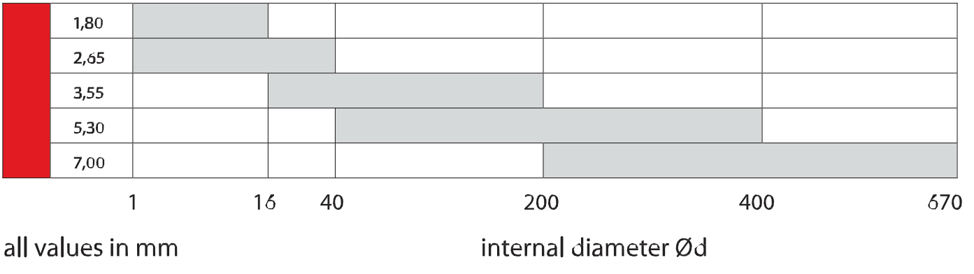
the accurate o-rings may be obtained according to various local and foreign standards. these standards recommend the thickness of o-rings H dependent to internal diameter of o-ring Ød.
standard production program
| standard | recomended sizes of o-rings (mm) | |
| internal diameter Ød | thickness H | |
| PN 029280 Moveable | 4 – 25 | 2,3 |
| 20 – 46 | 4.6 | |
| 40 – 120 | 5.8 | |
| 110 – 490 | 8.6 | |
| PN029281-Static | 6 – 100 | 2 |
| 50 – 480 | 3 | |
| 105 – 480 | 5 | |
| U.S. STANDARD | 1.78 – 133.07 | 1.78 |
| (AS 568A) | 1.24 – 247.32 | 2.62 |
| 4.34 – 456.06 | 3.53 | |
| 10.46 – 658.88 | 5.33 | |
| 113.67 – 658.88 | 6.99 | |
| swedish standard | 3.1 – 37.1 | 1.6 |
| (SMS 1588) | 3.3 – 17.3 | 2.4 |
| 19.2 – 144.3 | 3.0 | |
| 44.2 – 499.3 | 5.7 | |
| 144.1 – 249.1 | 8.4 | |
| french | 2.4 – 8.9 | 1.9 |
| standard | 8.9 – 18.4 | 2.7 |
choice of the o-ring size
the selected thickness H should be proportional to the o-ring internal diameter Ød. the dimensions in the table may be considered as the guide. these values correspond to the DIN 3771, Part 1. with regard to the tolerances we recommend if in doubt to use the nearest greater thickness. this should be taken into account mainly for dynamic applications. for static applications, the greater diameter of the o-ring with the lower thickness may be reliably used.
compression and deformation
depression and deformation
the elastomers feature under the load not only elastic, but also permanent deformation. this is also one of important parameters for determination of the o-ring sealing properties. the permanent deformation is determined according to the DIN 53517 of ASTM 395 B as follows:
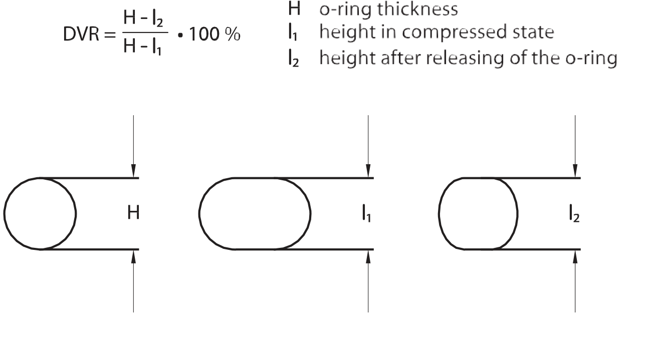
initial compression
initial compression of the o-ring in the groove is necessary for ensuring of its function as the primary or secondary sealing element. it serves for: – achieving of initial sealing capacity
- ensuring of certain friction force
- compensation of permanent deformation
- compensation of wearing
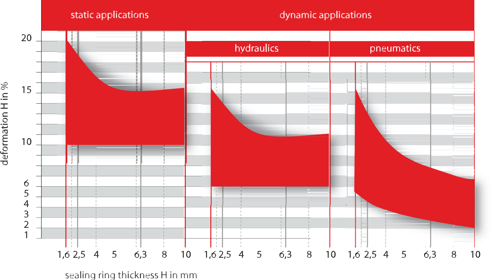
dependant to the application the following values of the initial compression as the quotient of the thickness H may be in simplified way used: dynamic application 6 to 20 %
static application 15 to 30 %
if we take into account the tolerances of the o-ring and the groove, then the minimal values of the initial compression for hydraulic is 6 % and for pneumatic is 2 %.
recommended compression
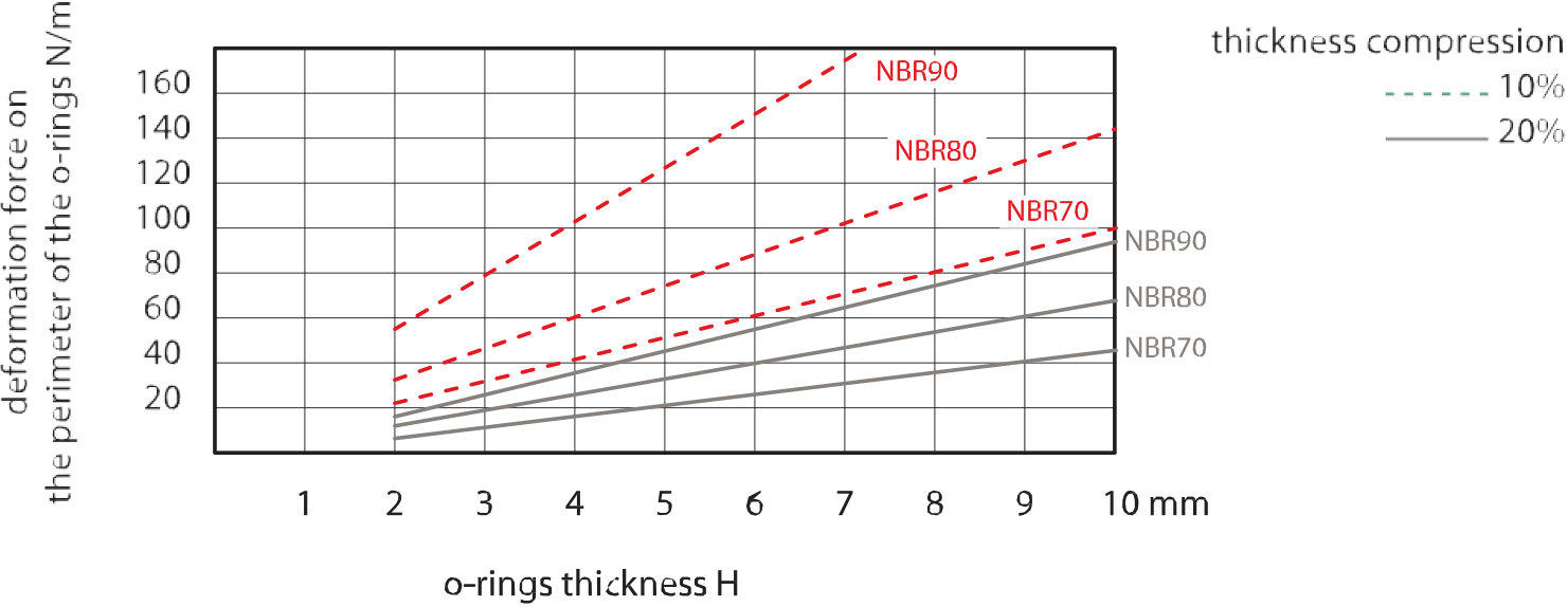
deformation forces
the deformation forces differ in relation to the initial compression and hardness of the material. the following graph displays the unit deformation force per one centimetre of the sealant perimeter as the function of its thickness (H) in relation to the material hardness.
the value of the deformation force may be used for estimation of the total force necessary for the static installation of the o-ring.
elongation and compression, surface
elongation and compression
in radial arrangement, when the o-ring in the groove seals by its outer diameter, it should be elongated on its internal diameter. the maximal elongation for installation is 6 %.
in case of outer groove – sealing by internal diameter – it is suitable to compress the o-ring along its perimeter. the maximal perimeter compres- sion for installation is 3 %.
exceeding of the values results in excessive increase or decrease of the o-ring thickness. the elongation of 1 % corresponds to thickness (H) de- crease of cca 0.5 %.
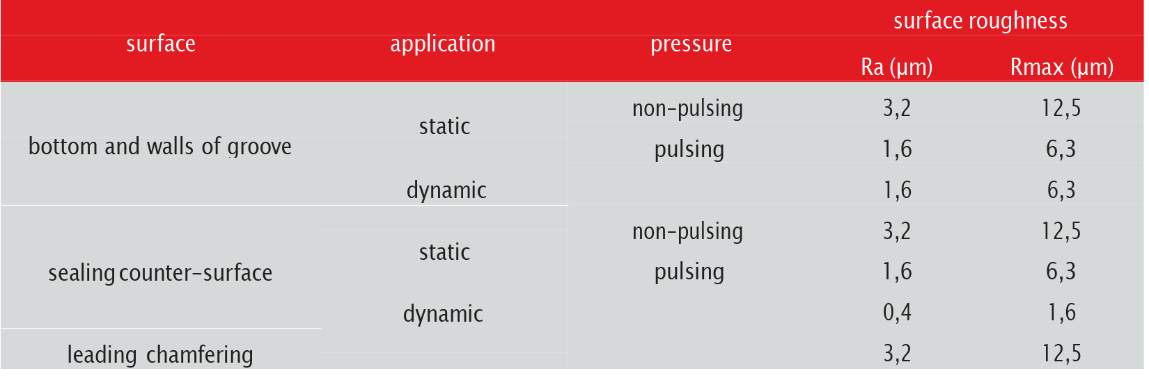
surface
at compression, the elastomers adjusts to the uneven surface. it means the tightness for gas and liquid, but there is however certain minimal set of requirements for the quality of surface to be sealed.
scratches, holes, concentric or spiral traces of machining are not allowed. higher requirements must be set to dynamic sealed surfaces as com- pared with the static applications.
presently there are no unified definitions for description of the surface quality. the values of mean arithmetic surface deviation Ra are not sufficient for practical determination of the surface quality. also the maximal height of the profile unevenness Rmax must be taken into account.
the values provided for in the table serve for recommendation for most allowable sealing applications and are based on the ISO 3601-2 standard.
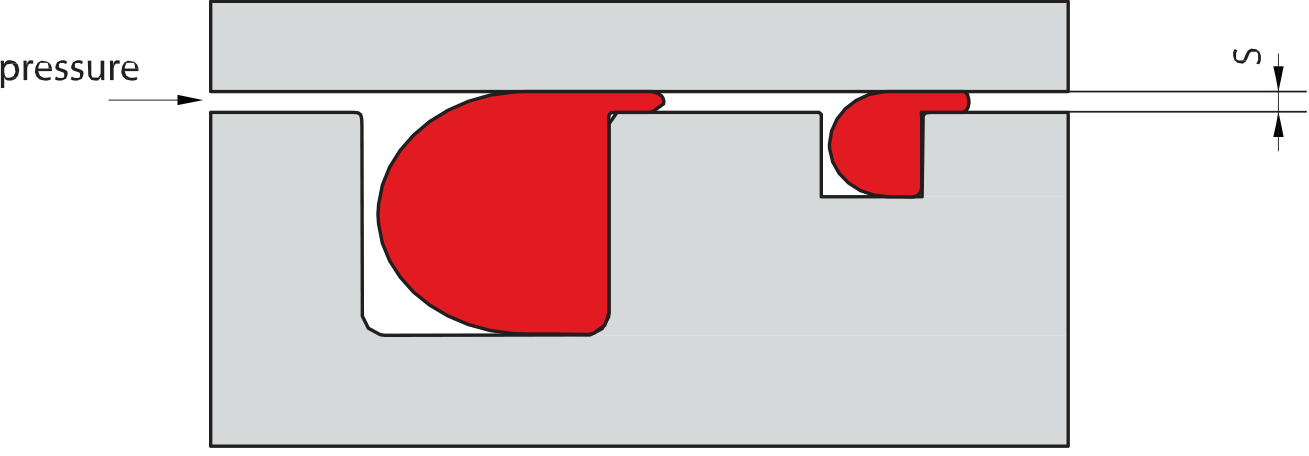
radial clearance – gap
allowed radial clearance s between sealed components depends on the pressure in the system, thickness and hardness of the o-ring. too large clearance means danger of extrusion of the sealant into the gap and subsequent damage of the o-ring.
following approximate values if hardness are suitable to select during choice of the material for application without female adapter: hardness max. pressure
70 Shore A < 100 bar
80 Shore A < 200 bar
90 Shore A < 400 bar
if it is feasible from the design point of view, the technically most suitable solution is to use to material of the middle hardness together with the female adapter.
following table may be used as a guide. It contains the max. allowed gaps as the function of the o-ring thickness and its hardness. the graphs may be also used for quick reference.
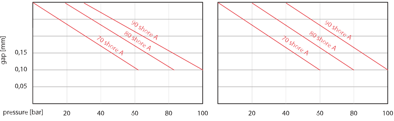
these values apply under condition, that the sealed components are aligned concentrically and do not extend themselves under pressure. in case it may not be guaranteed, the gap should be proportionally decreased. for static applications, we recommend the alignment H7/g6 or H7/f6.
the table and the graphs are valid for elastomer materials except the polyurethane and coated o-rings. the polyurethane o-rings enable to use the larger gaps due to their high resistance against extrusion and due to dimensional stability.
other possible manner of the o-ring protection against extrusion into the sealed gap is adding of female adapters. the female adapters are recom- mended for pressures above approximately 10 MPa or in case of larger sealed gaps.
the selection of sets includes two types of back-up rings:
- split ring, preferred for applications with sealing outer diameter
- non-split ring, preferred for sealing by internal diameter and for split grooves.
standard material for the female adapters is pure PTFE .upon request, also the special materials may be used.
in case of special applications contact our technical department.
design recommendations
general recommendations
before the installation itself, check the assembly area of the sealing o-ring for any sharp edges, transverses, traces after machining, threads, tra- verse drilling, chips or foreign particles. verify, if the leading chamfering are made according to the drawings. make sure before lubricating by grease or oil on the compatibility of the lubricant with the elastomer material, and whether the lubricant does not contain solid particles such as molybdendisulphite or zincsulphite. check, whether the ring is not deformed by extensive twisting.
recommendation for installation
leading chamfering
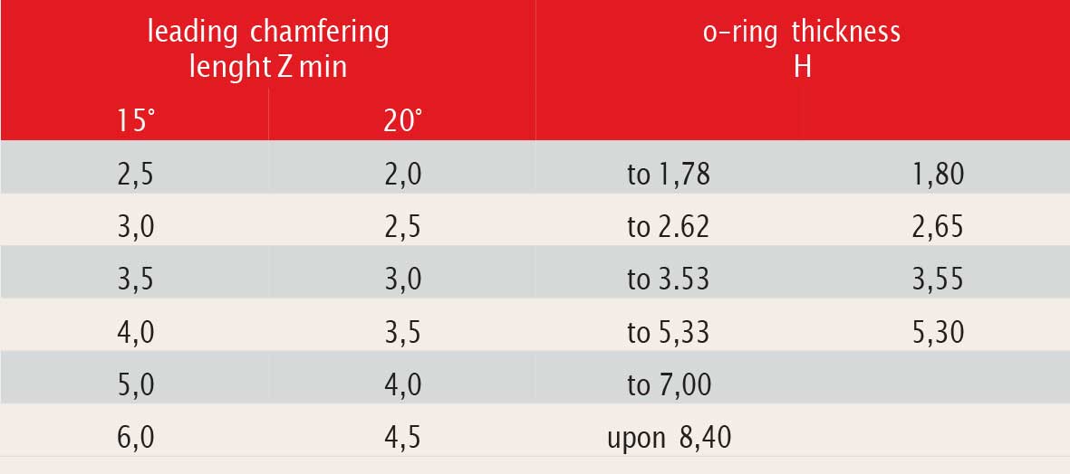
the proper design may eliminate possible damage of the sealant at the beginning. regarding the initial compression of the o-ring thickness must have leading chamfering and its edges must be rounded. minimal lengths of the leading chamfering are stated in the table.
manual assembly
- do not use sharp tools
- make sure the ring is not twisted
- use the assembly adds whenever possible
- do not overload the o-rings, especially made by the sticking of the cord
automatic assembly
the automatic assembly requires the good and proper assembly. the surface of the o-rings is usually treated by molybdenum disulphide, graph- ite, talcum or PTFE coating. the treatment decreases the forces necessary for assembly, prevents the „sticking“ and make the removing easier. for detailed information contact our technical department.
tolerances
during vulcanising, the dimensional changes of the o-rings from elastomers may occur due to their shrinkage. the shrinkage level depends on material, die shape and vulcanising process.
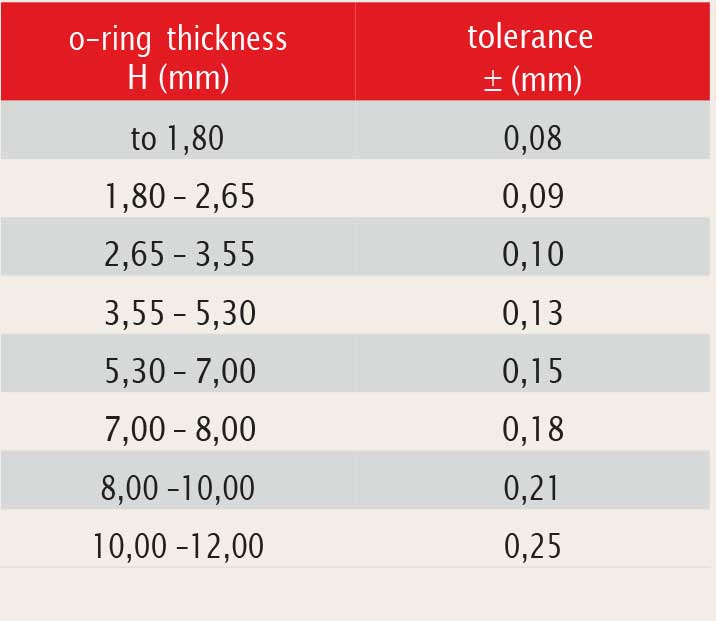
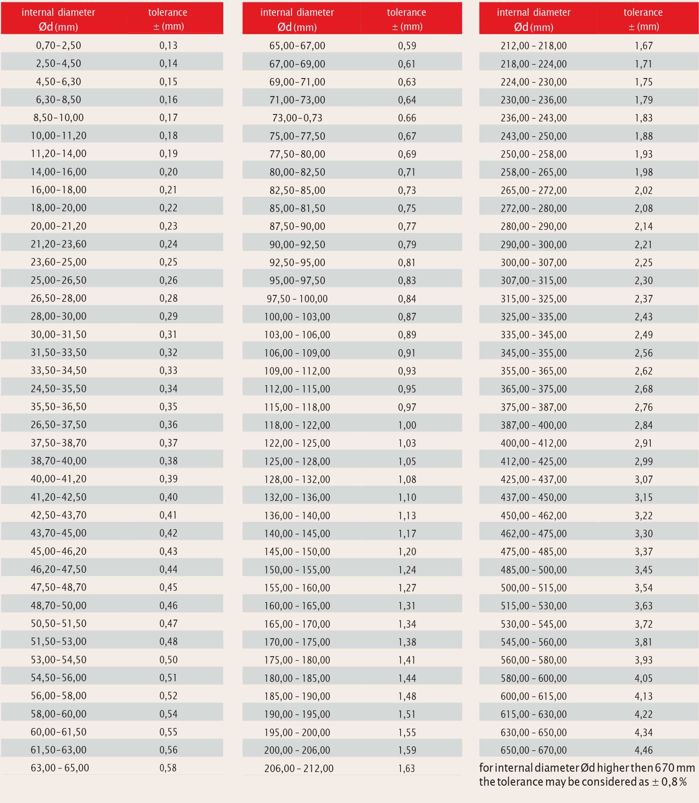
following tables state the tolerances of thickness H and internal diameter Ød. the tables apply for all elastomer mixtures NBR of the hardness 70 shore A. other mixtures may feature different dimensional characteristics. in most cases the tolerance have no influence the sealing function. also the o-rings of high precision are available. if needed contact our technical department. the o-rings, whose dimensions are not stated in the tables, are produced in tolerances according to the ISO 3601/DIN 3771 standard.
thickness tolerances
diameter tolerances
quality criteria for o-rings
definition of the quality criteria significantly influences the effective costs for used sealants. the selection of the material according to the quality sign influences the costs and reliability of usage. the ISO 3601/3 – DIN 3771/4 standards define allowable deviations of the shape and surface. in the table, there is stated the classification of defect sizes according to the quality signs.
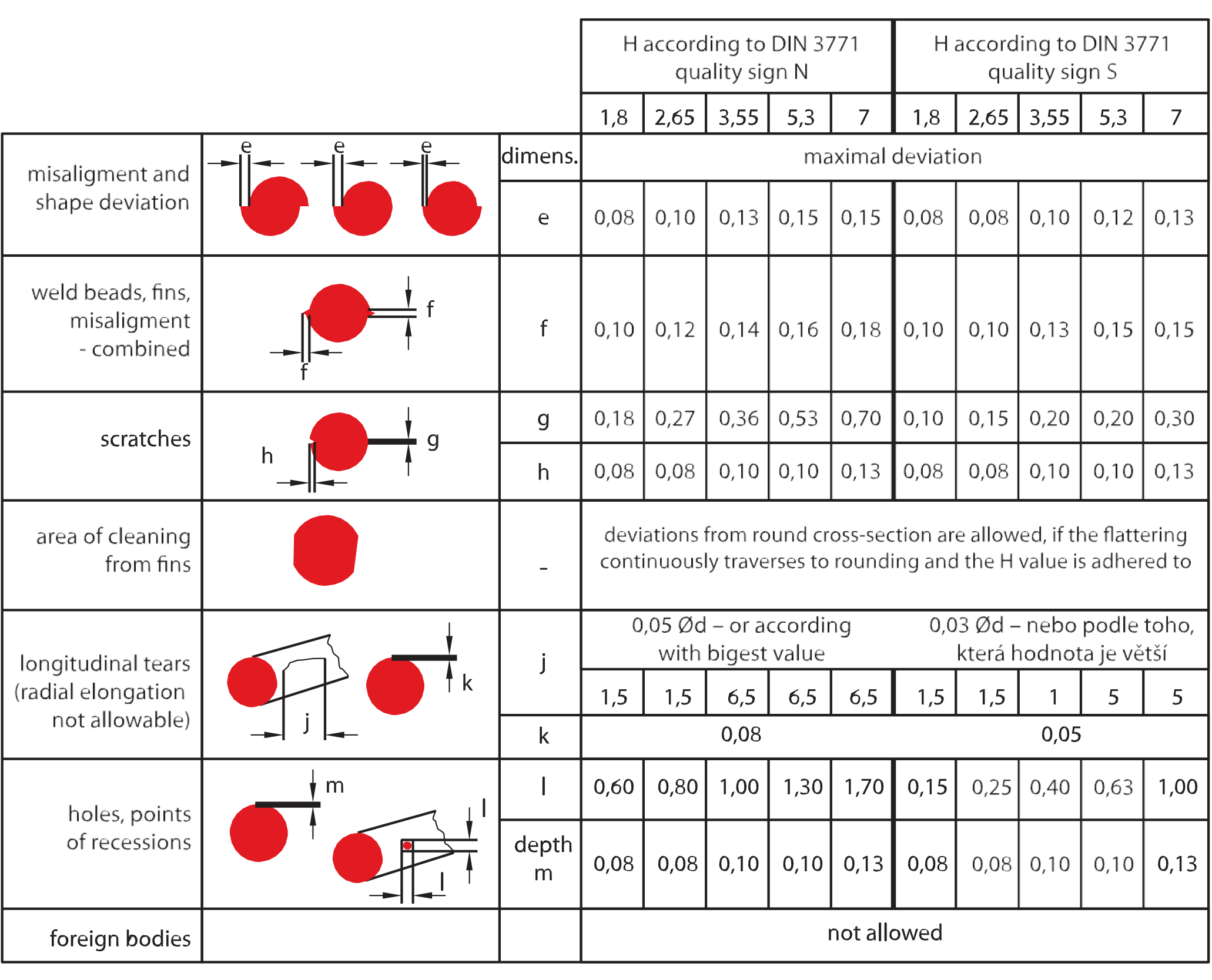
quality sign N
the o-rings of this sign adhere to the requirements for standard quality. they satisfy the requirements for static and dynamic sealing
quality sign S
o-rings of this sign are subject to exceptional requirements, e.g. for important safety components in automotive industry. the allowed sizes of the defects are very limited. it requires more demanding technology and strict quality check.
unless other requirements are specified, the seal-mart company delivers the o-rings with the quality sign N.
installation methods, shape of groove
shape of groove
in all new designs, the rectangular groove is preferred. the chamfer up to 5 ° is allowed at their sides.
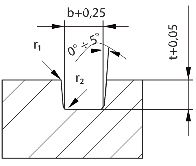
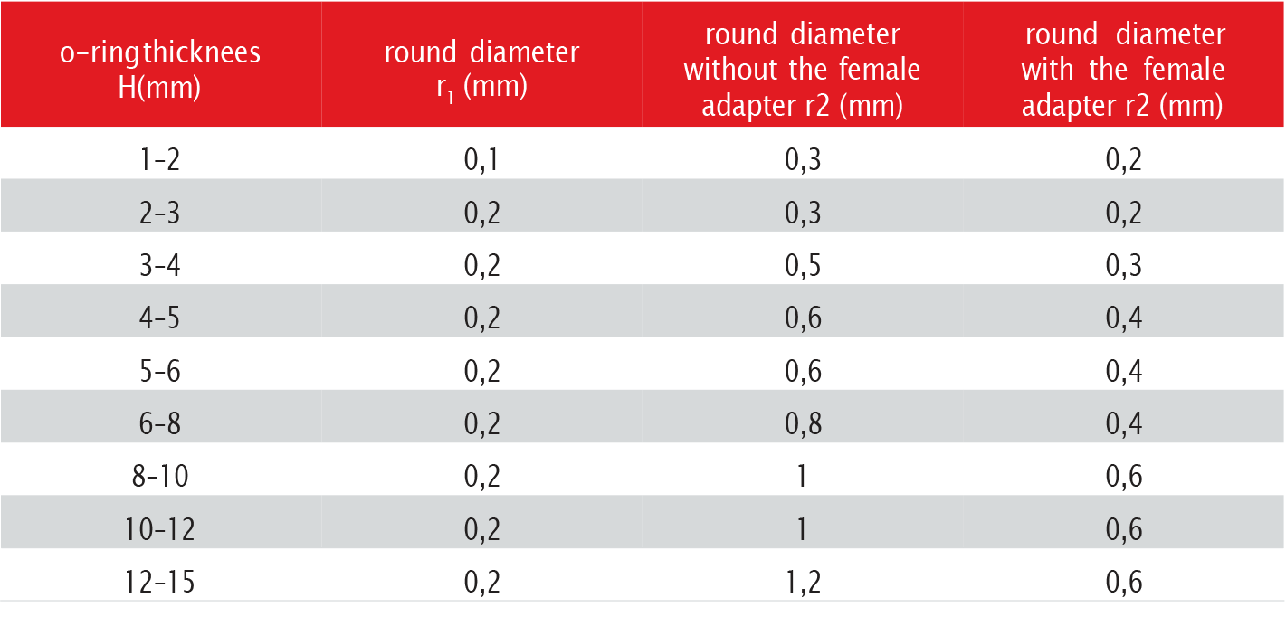
the back-up rings requires however the sides without the chamfer. the groove widths must respect the values of the o-ring swellings, which are determined by the DIN 3771/5 standard. this standard allows the 8 % swelling of o-rings for dynamic applications and 15 % for static applications. the round diameters r1 and r2 are stated in following table.
round diameters of the edges of rectangular groove in relation to the thickness of the o-ring H.
in the pneumatic applications, the same criteria for the sealing o-rings apply as for the hydraulic applications. there are lower pressures, but the lubrication is not so optimal as in hydraulic. due to lower forces, it is necessary to decrease the initial compression of the o-ring. this will achieve the decrease of the initial friction. the depth of the groove t1 must be adjusted.
installation methods, radial installations, axial installations
seal & housing recommendations
please note that we are able to produce those profiles to your specific need or any non standard housing. for detail measurements, please see seal-mart catalog…
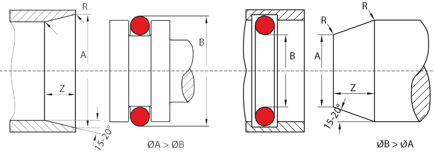
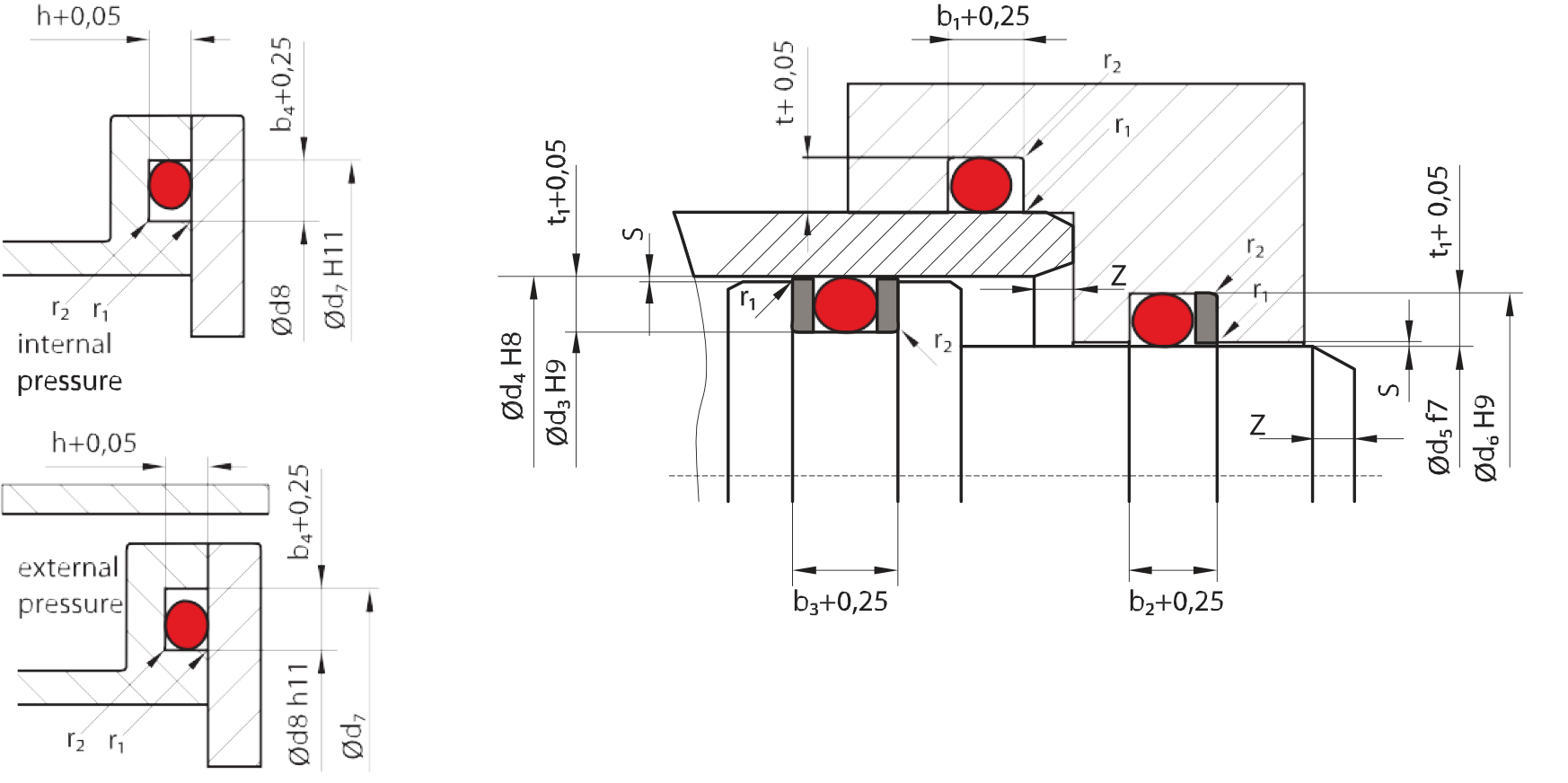
selection of o-ring diameter Ød Radial installation (static, dynamic)
sealing by internal diameter
the o-ring size should be selected in such manner, that the internal diameter Ød should have the least deviation from the sealed diameter d5.
sealing by external diameter
the o-ring size should be selected in such manner, that the internal diameter Ød should be the same or smaller then the grove diameter d3
axial instalation (static)
selection of the o-ring size for axial installation must take into account the direction of the pressure applying. in case of internal pressure the o- ring should be greater of 1-2 % then the external diameter of the groove d7. for the external pressure, the o-ring should be selected to be of 1-3% smaller then the internal diameter of the groove d8.
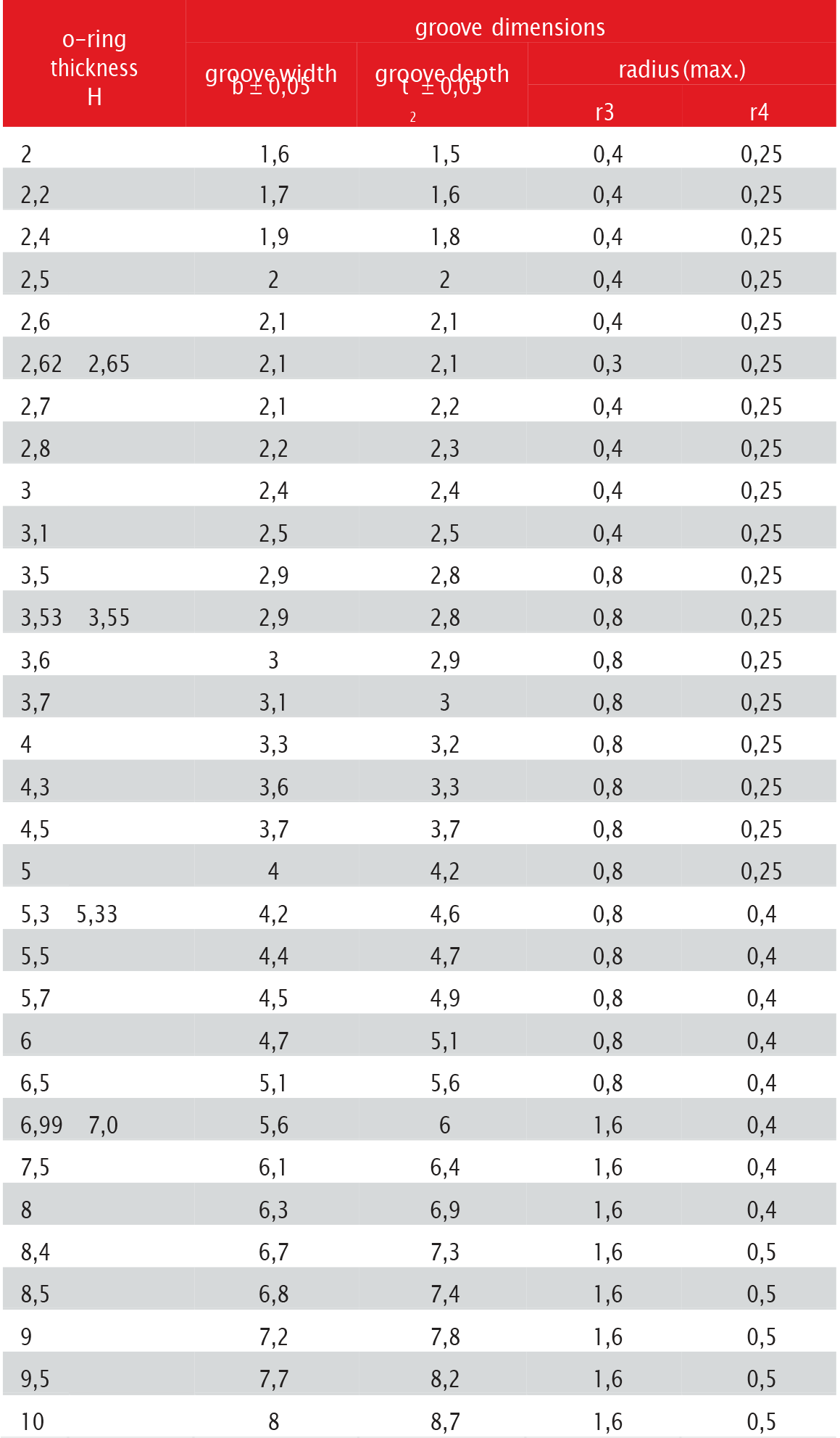
the built-up dimensions stated in the following table are valid for o-rings from the NBR material of ca 70 Shore A. elastomers with larger shrinkage,
such as MVQ or FKM, the groove depth should be decreased. in such cases contact our technical department.
installation methods, recommended tolerances

installation methods
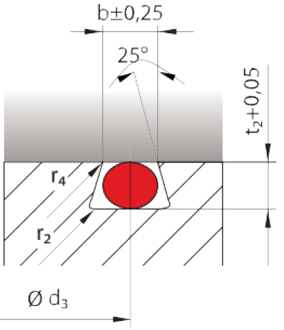
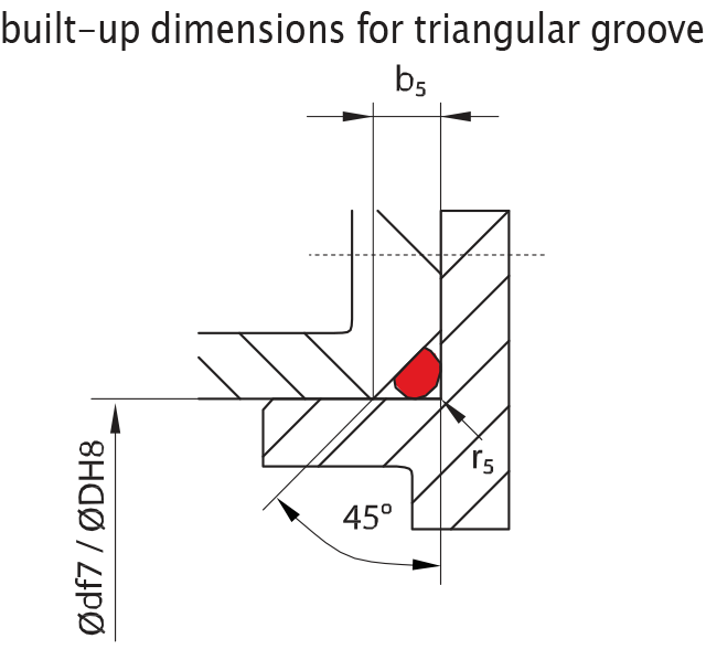
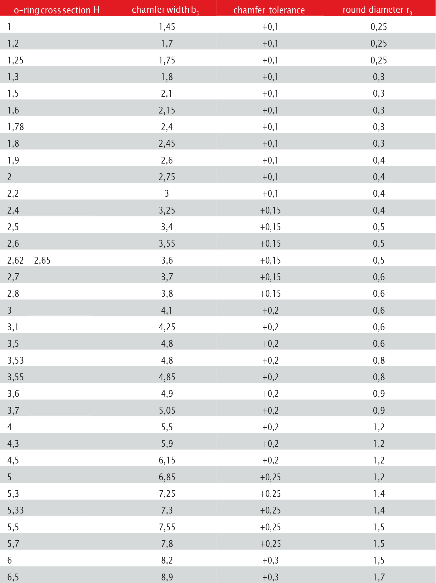
trapezoidal groove
the trapezoidal groove should be used only in exceptional cases, when the o-ring must be firmly fixed in the groove. it may be e.g. installation into the groove upside down. the built-up dimensions are stated in the table. the trapezoidal groove is recommended only for o-rings with the thick- ness above 2.5 mm, in exceptional cases from 2 mm. the size of the o-ring is determined according to the relation Ød = d3 – H
installation dimension for trapezoidal groove
special o-rings
FEP encapsulated o-rings
the o-rings coated with special material FEP contain the internal ring from the elastic elastomer with lower resistance – especially against chemical influence. the elastomer ensures the required elasticity. the outer coating from fluorided ethylene-propylene provides the o-rings with the hard- ness, low friction and mainly excellent chemical resistance, which is not achievable by the common elastomer.
the operating temperatures range from –60 °C to +200 °C. it is limited by the internal ring diameter. this temperature range and physiological safety of the material permit to sterilise all equipments fitted with the coated o-rings. therefore, the usage in food and pharmaceutical industry, during the production of beverages and in medical technologies, is possible.
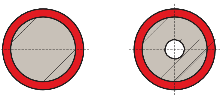
the coated o-rings are produced in two versions – with full internal elastomer and with hollow elastomer.
perfluoro rubber o-rings
the rings made from the material of entirely exceptional properties – perfluor rubber (FFKM) – are considered also for the special o-rings.
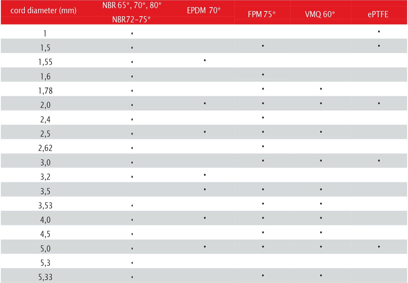
packing cords (R13-cord/o-ring cord)
in some special cases the round cords may be used with advantage. the o-ring for static application of any dimensions may be made from the cord with required diameter by sticking or by vulcanising. the cords are availabl e as the meter goods. in following table, there is overview of dimensions and materials of the o-rings, which are offered by the seal-mart company .

chemical compatibility
chemical compatibility – overwiew
this overwiew of suitability materials contains for different elastomers supplied by us the valuation of chemical resitance against operating me- diums. following data comes from experiments and data of our suppliers and customers. with the respect to the different application conditions is needed these data take for the guidedata, which are not obligatory and must be verified in every single case. all the data applies to the room temperature.
A–E rating system:
A = 0–5 % chemical swelling, elastomer shows little or no effect from exposure. very good suitability B = 5–10 % chemical swelling, elastomer shows some effect from exposure. good suitability
C = 10–20 % chemical swelling.The loss of physical properties after exposure. limited suitability D = unsuitable E = insufficient information for use