

description
two piece PS 08-A comprising one profile ring with pronounced sealing edge and one contact pressure element for producing the pre-load.
category of profile
machined or molded/standard/trade product.
double acting
the PS 08-A seal is designed for use as a piston seal.
area of application: hydraulics
- earth moving equipment, agricultural machinery, injection moulding machines, industrial vehicles, cranes, loading platforms.
- the PS 08-A profile is suitable for use in all standard industrial cylinders as well as in farming equipment, light construction machinery and mobile devices. due to the exceptionally high dynamic sealing performance, it is particularly suited for leakage critical applica- tions such as steering cylinders.
advantages
- good static and dynamic tightness.
- low friction, smooth movement even at low running speeds.
- contact pressure element with rectan gular cross-section, prevents twisting in the housing.
- standardised housings according to ISO 7425.
- low axial housing heights.
operating parameters & material
| material | temperature | max. surface speed | max. pressure 1 | hydrolysis | dry running | wear resistance | |
| sealing element | energizer | ||||||
| PU (98 Shore A) | NBR 72 Shore A for D ≤63 | -30 °C … +100 °C | 0.5 m/s | 400 bar (40 MPa) | – | + | ++ |
| PU (98 Shore A) | NBR 80 Shore A for D ≤63 | -30 °C … +100 °C | 0.5 m/s | 400 bar (40 MPa) | – | + | ++ |
| PU (60 Shore D) | NBR 80 Shore A | -35 °C … +110 °C | 0.5 m/s | 250 bar (25 MPa) | – | + | ++ |
important note:
the above data are maximum values and can’t be used at the same time. e.g. the maximum operating speed depend on material type, pressure, temperature and gap value. temperature range also dependent on medium.
1 pressure ratings are dependent on the size of the extrusion gap.
gap dimension
the largest gap dimension occurring on the non-pressurised side of the seal in operation is of vital importance for the function of the seal.
| operating pressure | cs = (ØD – Ød)/2 mm | ||||
| 3.2 | 4.2 | 6.3 | 8.1 | 10.5 | |
| max. permissible gap dimension | |||||
| 16 | 0.30 | 0.40 | 0.50 | 0.60 | 0.65 |
| 26 | 0.20 | 0.30 | 0.50 | 0.50 | 0.55 |
| 32 | – | 0.20 | 0.30 | 0.40 | 0.45 |
| 40 | – | – | 0.25 | 0.35 | 0.40 |
important note:
the above data are maximum value and can’t be used at the same time. e.g. the maximum operating speed depend on material type, pressure, tem- perature and gap value. temperature range also dependent on medium.
surface quality
| surface roughness |
Rtmax (μm) |
Ra (μm) |
| sliding surface | ≤2,5 | ≤0,05-0,3 |
| bottom of groove | ≤6,3 | ≤1,6 |
| groove face | ≤15 | ≤3 |
tolerance recommendation
the admissible gap width, tolerances, guide play and deflection of the guide under load are to be taken into account when designing ø piston.
| seal housing | tolerances |
| Ød | h9 |
| ØD | H9 |
fitting & installation
careful fitting is a prerequisite for the correct function of the seal.
the cylinder bore must have a leading edge chamfer. profile K08-SD can be snapped into closed grooves.
seal & housing recommendations
please note that we are able to produce those profiles to your specific need or any non standard housing. for detail measurements, please see Jet seal pars catalog…
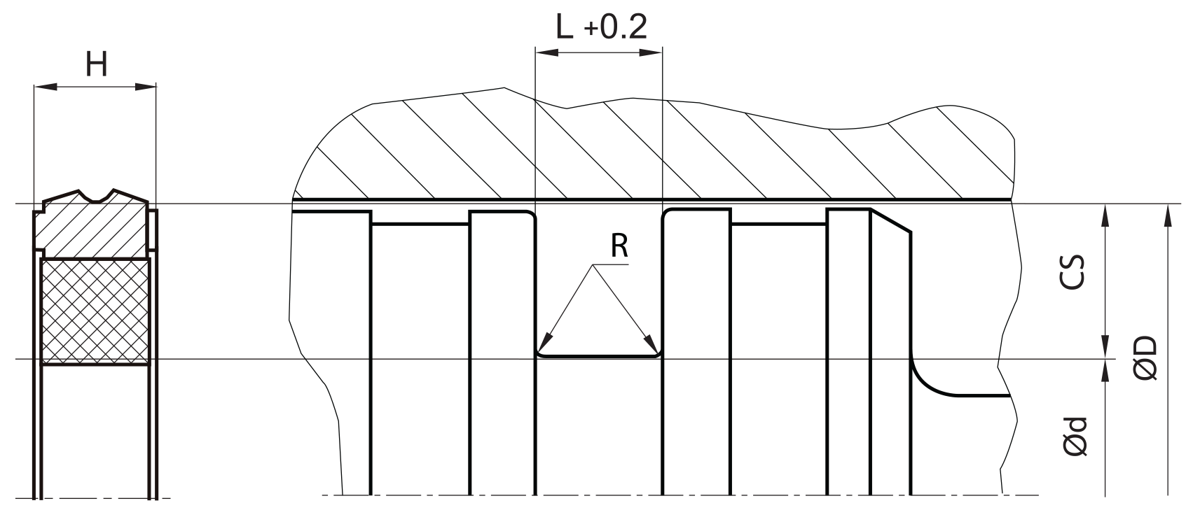
| L | R |
| ≤ 10 | max. 0,4 |
| > 10 …..≤ 1,5 | max. 0,8 |
| > 15 | max. 1,2 |
don’t hesitate to contact our technical department for further information or for special requirements (temperature, speed etc.), so that suitable materi- als and/or designs can be recommended.