

description
O-Ring activated symmetric PU piston seal with excellent static and dynamic sealing capacity, remely wear resistant.
- asymmetric double-acting composite piston seals, with a gliding part made of excellent wear resistant polyurethane and an elastic preload element.
- interference fit on the inside diameter.
- various materials are available for different purposes.
- snaps into simple grooves (see notes on installation).
- the free space on the trailing side reduces the risk of gap extrusion.
- highest degree of sealing across a wide temperature range.
- for pressures up to 250 bar as a seal between pressurised space and atmosphere.
- excellent sealing in all pressure ranges.
- excellent static and dynamic sealing.
- suitable for short and long travel with extremely slow or quick movements.
- no stick-slip.
- small break-awayload after prolonged periods of standstill.
- suitable for holding functions.
- no drag pressure build-up.
- radial grooves assure a fast pressure activation of the seal (design and arrange-
- because of the excellent sealing effect a fluid transport between the pressurised spaces is practically prevented.
application
category of profile
machined or molded/standard/trade product.
double acting
the PS 08-AD seal is designed for use as a piston seal.
area of application: hydraulics
- reciprocating pistons on hydraulic cylinders, small swivelling motion permissible. as piston seal at simple designs in medium pressure range.
- dimensions according to ISO 7425 part 1 are common, as well as standard types that differ slightly in the depth of the mounting space. for specific dimensions see “range of profile sizes”.
note
the calculation program is based on mounting spaces according to ISO 7425, part 1. intermediate sizes are possible, with an O-ring for standard sizes. for deviating dimensions choose a different profile.
function
PS 08-AD profiles are composite piston seals designed to seal between two pressurised spaces; mainly for reciprocating movements. the design is based on application in standard hydraulic systems with conventional hydraulic oils.
the operating parameters are as defined in the sealing data sheet and material data. requirements deviating from these parameters can be met to a certain degree by changing the geometry in the software program.
operating parameters & material
| material | temperature | max. surface speed | max. pressure 1 | hydrolysis | dry running | wear resistance | |
| sealing element | energizer | ||||||
| PU | NBR | -30 °C … +100 °C | 1 m/s | 250 bar (25 MPa) | – | + | ++ |
| HPU | NBR | -20 °C … +100 °C | 1 m/s | 250 bar (25 MPa) | – | + | ++ |
| SPU | NBR | -20 °C … +100 °C | 1 m/s | 250 bar (25 MPa) | – | + | ++ |
| LTPU | NBR | -30 °C … +100 °C | 1.4 m/s | 250 bar (25 MPa) | – | ++ | ++ |
| GPU | NBR | -30 °C … +100 °C | 1 m/s | 250 bar (25 MPa) | – | + | ++ |
the stated operation conditions represent general indications. it is recommended not to use all maximum values simultaneously. surface speed limits apply only to the presence of adequate lubrication film.
1 pressure ratings are dependent on the size of the extrusion gap.
++ … particularly suitable o … conditional suitable
+ … suitable – … not suitable
for detailed information regarding chemical resistance please refer to our „list of resistance“. for increased chemical and thermal resistance rubber
materials in other systems are to be preferred, attention should be paid to restrictions for pressure range and wear resistance. for higher gliding speeds another system should be used (e.g. PTFE materials).
note on special materials:
as temperature limit and chemical resistance are determined by the preload element, the temperature range can be increased and the resis-
tance to chemical influences improved, if a special material is used for the preload element.
gap dimension
| operating pressure | cs = (ØD – Ød)/2 mm | ||||||
| 2.45 | 3.75 | 5.5 | 7.75 | 10.5 | 12.25 | 14 | |
| safe extrusion gap (mm) | |||||||
| 100 bar (10 MPa) | 0.27 | 0.33 | 0.38 | 0.43 | 0.50 | 0.55 | 0.60 |
| 200 bar (20 MPa) | 0.19 | 0.25 | 0.28 | 0.33 | 0.37 | 0.43 | 0.45 |
| 300 bar (30 MPa) | 0.17 | 0.20 | 0.22 | 0.25 | 0.30 | 0.34 | 0.38 |
| 400 bar (40 MPa) | 0.16 | 0.18 | 0.19 | 0.21 | 0.25 | 0.28 | 0.30 |
important note:
the above data are maximum value and can’t be used at the same time. e.g. the maximum operating speed depend on material type, pressure, tem- perature and gap value. temperature range also dependent on medium.
the diagram applies to an operating temperature of 70 °C.
surface quality
| surface roughness |
Rtmax (μm) |
Ra (μm) |
| sliding surface | ≤2,5 | ≤0,1-0,5 |
| bottom of groove | ≤6,3 | ≤1,6 |
| groove face | ≤15 | ≤3 |
tolerance recommendation
| seal housing | tolerances |
| Ød | h10 |
| ØD | H9 |
recommended housing for K08-P
| L | (ØD – Ød)/2 mm |
| 3.2 | 3.75 |
| 4.2 | 5.50 |
| 6.3 | 7.75 |
| 10.50 | 8.1 |
mode of installation:
the seal can generally be snapped over the piston by hand without problems.
recommended mounting space:
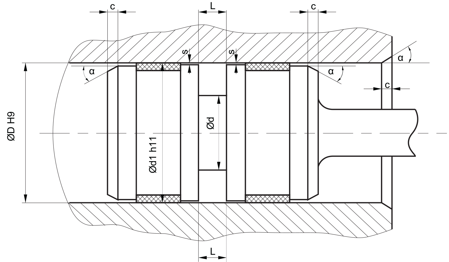
insertion chamfer:
in order to avoid damage to the piston seal during installation, the piston and the housing is to be chamfered and rounded as shown in the “recommended mounting space” drawing. the size of chamfer depends on the seal type and profile width.
| cs (mm) | c (mm) | |
| α = 15⁰ … 20⁰ | α = 20⁰ … 30⁰ | |
| 2.45 | 2.5 | 1.5 |
| 3.75 | 3.5 | 2 |
| 5.5 | 4.5 | 3 |
| 7.75 | 5 | 3.5 |
| 10.5 | 6 | 5 |
| 12.25 | 8 | 6 |
instead of a chamfer, the piston can also be designed with a radius. recommended size of the radius is equal to size of chamfer (R=c).
seal & housing recommendations
please note that we are able to produce those profiles to your specific need or any non standard housing. for detail measurements, please see Jet seal pars catalog…
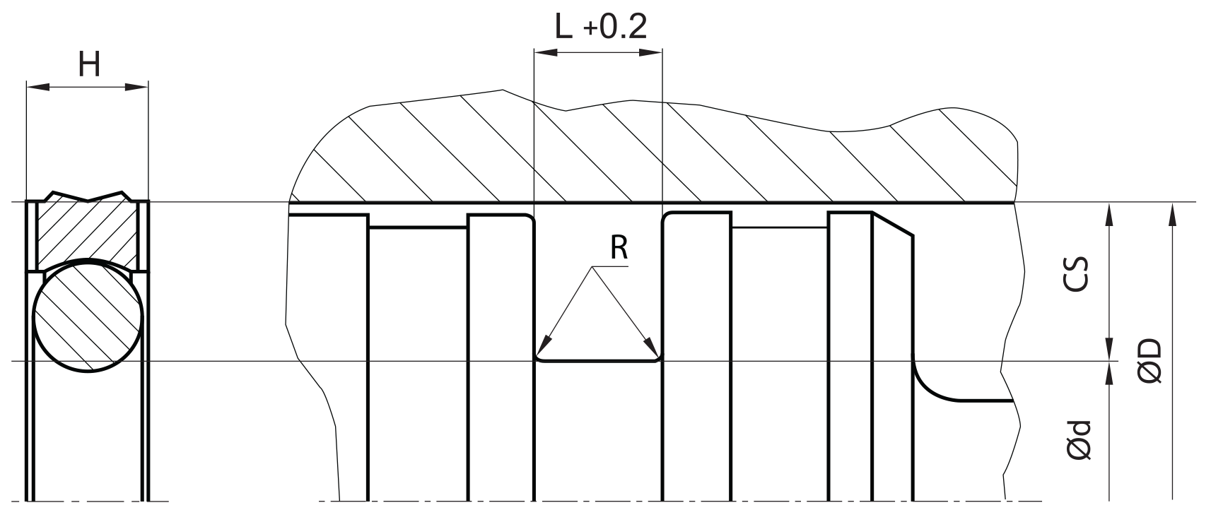
the ratio between nominal width and seal height should be in accordance to ISO 7425 part 1. we recommend the following values:
| ØD [mm] | ØD [mm] | L [mm] | cs = (ØD – Ød)/2 [mm] |
| 8 ~ 14,9 | ØD – 4,9 | 2,2 | 2.45 |
| 15 ~ 39,9 | ØD – 7,5 | 3.2 | 3.75 |
| 40 ~ 79,9 | ØD – 11 | 4.2 | 5.5 |
| 80 ~ 132,9 | ØD – 15,5 | 6.3 | 7.75 |
| 133 ~ 329,9 | ØD – 21 | 8.1 | 10.5 |
| 330 ~ 669,9 | ØD – 24,5 | 8.1 | 12.25 |
| L | (ØD – Ød)/2 mm |
| 3.2 | 3.75 |
| 4.2 | 5.50 |
| 6.3 | 7.75 |
| 10.50 | 8.1 |
fitted:
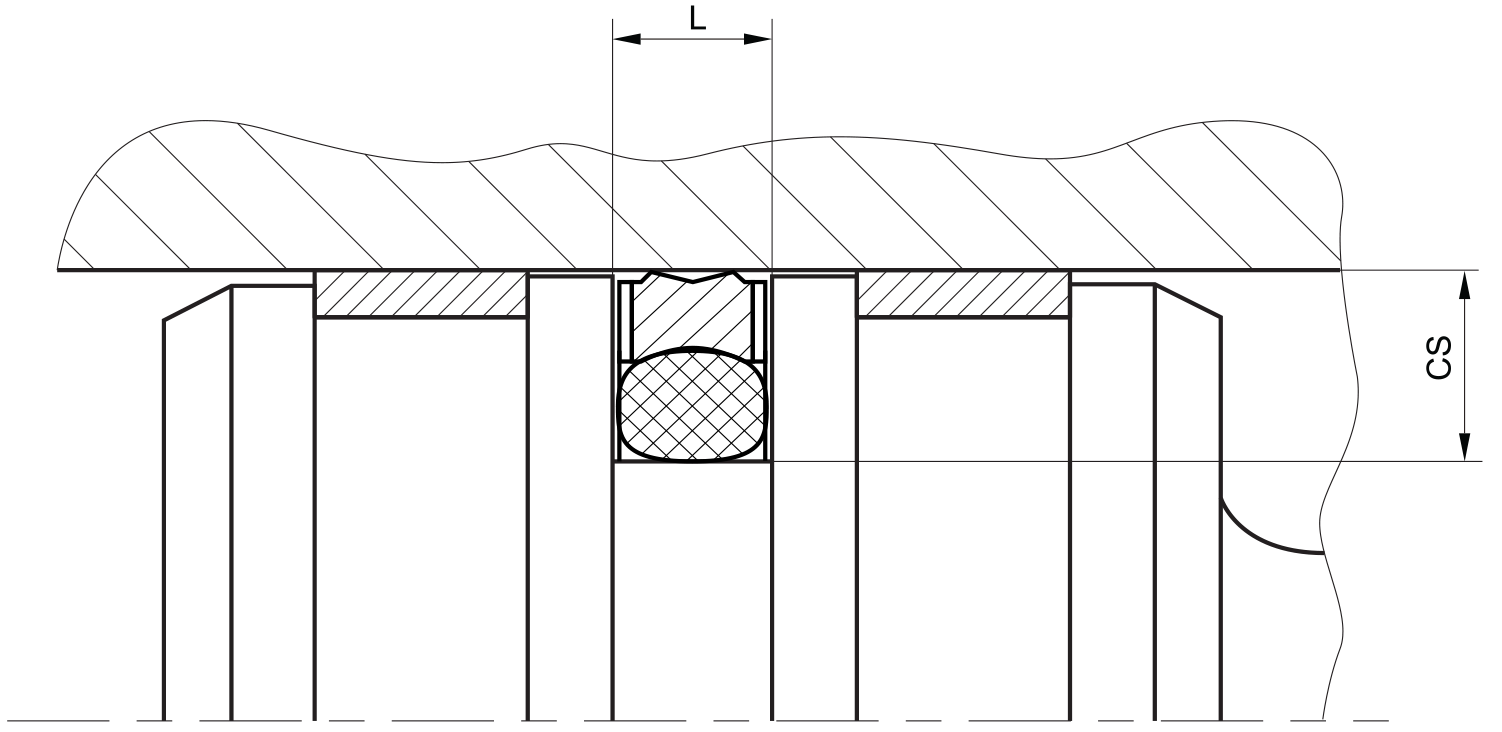
don’t hesitate to contact our technical department for further information or for special requirements (temperature, speed etc.), so that suitable materi- als and/or designs can be recommended.