

description
O-Ring activated asymmetric PTFE piston seal, low friction. for extreme lowor high speed.suitable for positioning functions. PS 08 can be used where a sealing piston has pressure on one side, amongst others, in standar-dised housings ac- cording to ISO 7425/1. Rod diameters in agreement with ISO 3320. Very high re- sistance to pressure and hardness, good thermal conductivity, very good protec- tion against extrusion, high resistance to abrasion, low friction, free of stick-slip.
- asymmetric single-acting composite piston seals, with a gliding part made of low-friction material and an elastic preload element.
- interference fit on the inside diameter.
- various materials are available for different purposes.
- snaps into simple grooves (see notes on installation).
- the free space on the trailing side reduces the risk of gap extrusion.
- highest degree of sealing across a wide temperature range.
- sealing effect enhanced by high recovery.
- for pressures up to 400 bar (in special cases up to 800 bar) as a seal between pressurised space and atmosphere.
- good sealing in all pressure ranges.
- good static and dynamic sealing.
- suitable for short and long travel with extremely slow or quick movements.
- no stick-slip.
- small break-awayload after prolonged periods of standstill.
- exact positioning due to little friction.
- high mechanical efficiency.
- insensitive to thermal damage caused by air in the oil.
- tandem arrangement possible (similar to S09-E).
application
not bolded symbols; please consult our technical for application limitations
category of profile
machined or molded/standard/trade product.
single acting
the PS 08-B seal is designed for use as a piston seal – either single or double acting where two seals are used ‘back to back’
area of application: hydraulics
- reciprocating rods on hydraulic cylinders,small swiveling motion permissible.
- as piston seal for small permissible frictional forces or if smooth running is required.
- for heavy-dutyoperating conditions, profile K08-ES is preferred.
note
the calculation program is based on mounting spaces according to ISO 7425, part 1. intermediate sizes are possible, with an O-ring for standard sizes. for deviating dimensions, use PS 08. attention must be given to a balanced ratio between sealing part and preload ele- ment.
function
PS 08-B profiles are composite piston seals designed to seal pressurised space against the atmosphere; mainly for reciprocating movements. the design is based on application in standard hydraulic systems with conventional hydraulic oils. the operating parameters are as defined in the sealing data sheet and material data. requirements deviating from these parameters can be met to a certain degree by changing the geometry in the software program.
operating parameters & material
| material | temperature | max. surface speed | max. pressure 1 | hydrolysis | dry running | wear resistance | |
| sealing element | energizer | ||||||
| PTFE glass | NBR | -30 °C … +100 °C | 10 m/s | 400 bar (40 MPa) | – | ++ | + |
| PTFE bronze | NBR | -30 °C … +100 °C | 10 m/s | 400 bar (40 MPa) | – | ++ | + |
| PTFE carbon | NBR | -30 °C … +100 °C | 10 m/s | 400 bar (40 MPa) | – | ++ | + |
| PTFE glass | FKM | -20 °C … +200 °C | 10 m/s | 400 bar (40 MPa) | – | ++ | + |
| PTFE bronze | FKM | -20 °C … +200 °C | 10 m/s | 400 bar (40 MPa) | – | ++ | + |
| PTFE carbon | FKM | -20 °C … +200 °C | 10 m/s | 400 bar (40 MPa) | – | ++ | + |
| PTFE glass | EPDM | -50 °C … +150 °C | 10 m/s | 400 bar (40 MPa) | ++ | ++ | + |
| PTFE bronze | EPDM | -50 °C … +150 °C | 10 m/s | 400 bar (40 MPa) | ++ | ++ | + |
| PTFE carbon | EPDM | -50 °C … +150 °C | 10 m/s | 400 bar (40 MPa) | ++ | ++ | + |
| PTFE glass | MVQ | -60 °C … +200 °C | 10 m/s | 400 bar (40 MPa) | ++ | ++ | + |
| PTFE bronze | MVQ | -60 °C … +200 °C | 10 m/s | 400 bar (40 MPa) | ++ | ++ | + |
| PTFE carbon | MVQ | -60 °C … +200 °C | 10 m/s | 400 bar (40 MPa) | ++ | ++ | + |
| UHMWPE | MVQ | -60 °C … +80 °C | 10 m/s | 400 bar (40 MPa) | ++ | + | + |
| XPU | NBR | -30 °C … +110 °C | 5 m/s | 600 bar (40 MPa) | |||
the stated operation conditions represent general indications. it is recommended not to use all maximum values simultaneously. surface speed limits apply only to the presence of adequate lubrication film.
1 pressure ratings are dependent on the size of the extrusion gap.
2 attention: not suitable for mineral oils!
++ … particularly suitable o … conditional suitable
+ … suitable – … not suitable
for detailed information regarding chemical resistance please refer to our “list of resistance”. for decreased leackage rates elastomer materials (polyure-
thane or rubber) in other sealing systems are to be preferred.
note on special materials:
as temperature limit and chemical resistance are determined by the preload element, the temperature range can be increased and the resis-
tance to chemical influences improved, if a special material is used for the preload element.
gap dimension
| operating pressure | cs = (ØD – Ød)/2 mm | ||||||
| 2.45 | 3.75 | 5.5 | 7.75 | 10.5 | 12.25 | 14 | |
| safe extrusion gap (mm) | |||||||
| 100 bar (10 MPa) | 0.27 | 0.33 | 0.38 | 0.43 | 0.50 | 0.55 | 0.60 |
| 200 bar (20 MPa) | 0.19 | 0.25 | 0.28 | 0.33 | 0.37 | 0.43 | 0.45 |
| 300 bar (30 MPa) | 0.17 | 0.20 | 0.22 | 0.25 | 0.30 | 0.34 | 0.38 |
| 400 bar (40 MPa) | 0.16 | 0.18 | 0.19 | 0.21 | 0.25 | 0.28 | 0.30 |
important note:
the above data are maximum value and can’t be used at the same time. e.g. the maximum operating speed depend on material type, pressure, tem- perature and gap value. temperature range also dependent on medium.
the table refers to a operating temperature of 80°C. temperatures below may increase the safe extrusion gap slightly, at temperatures above
80 °C, the gap dimensions has to be reduced or a stronger profile selected.
for extrusion gap sizes resulting from tolerance pair H8/f8 pressure ranges above 400 bar can be reached in special cases, influences due
to thermal expansion have to be considered. we recommend to contact our technical department.
surface quality
| surface roughness |
Rtmax (μm) |
Ra (μm) |
| sliding surface | ≤2,5 | ≤0,1-0,5 |
| bottom of groove | ≤6,3 | ≤1,6 |
| groove face | ≤15 | ≤3 |
tolerance recommendation
| seal housing | tolerances |
| Ød | h10 |
| ØD | H9 |
mode of installation
in case of closed grooves, it is not recommended to slip the seal over the piston by hand (uneven material deformation in the sealing part). after the O-Ring is placed into the groove, the sealing part should be stretched over a installation cone by using a sleeve (assembly aid tools).
a recovery of the sealing part with a calibrating sleeve is advisable, however, a special shaped insertion chamfer on the cylinder barrel can also be designed (danger of tilting).
values for “c” see insertion chamfer.
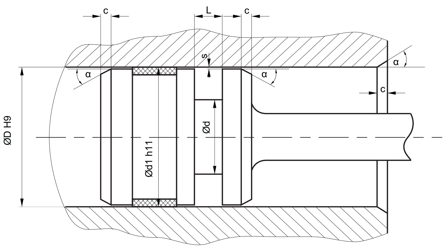
recommended mounting space:
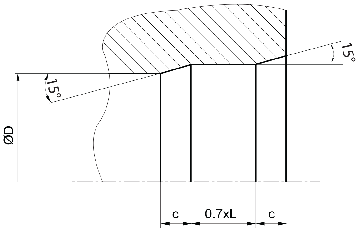
insertion chamfer:
in order to avoid damage to the piston seal during installation, the piston and the housing is to be chamfered and rounded as shown in the “recommended mounting space” drawing. the size of chamfer depends on the seal type and profile width.
| cs (mm) | c (mm) | |
| α = 15⁰ … 20⁰ | α = 20⁰ … 30⁰ | |
| 2.45 | 2.5 | 1.5 |
| 3.75 | 3.5 | 2 |
| 5.5 | 4.5 | 3 |
| 7.75 | 5 | 3.5 |
| 10.5 | 6 | 5 |
| 12.25 | 8 | 6 |
| 14 | 10 | 7 |
instead of a chamfer, the piston can also be designed with a radius. recommended size of the radius is equal to size of chamfer (R=c).
seal & housing recommendations
please note that we are able to produce those profiles to your specific need or any non standard housing. for detail measurements, please see Jet seal pars catalog…
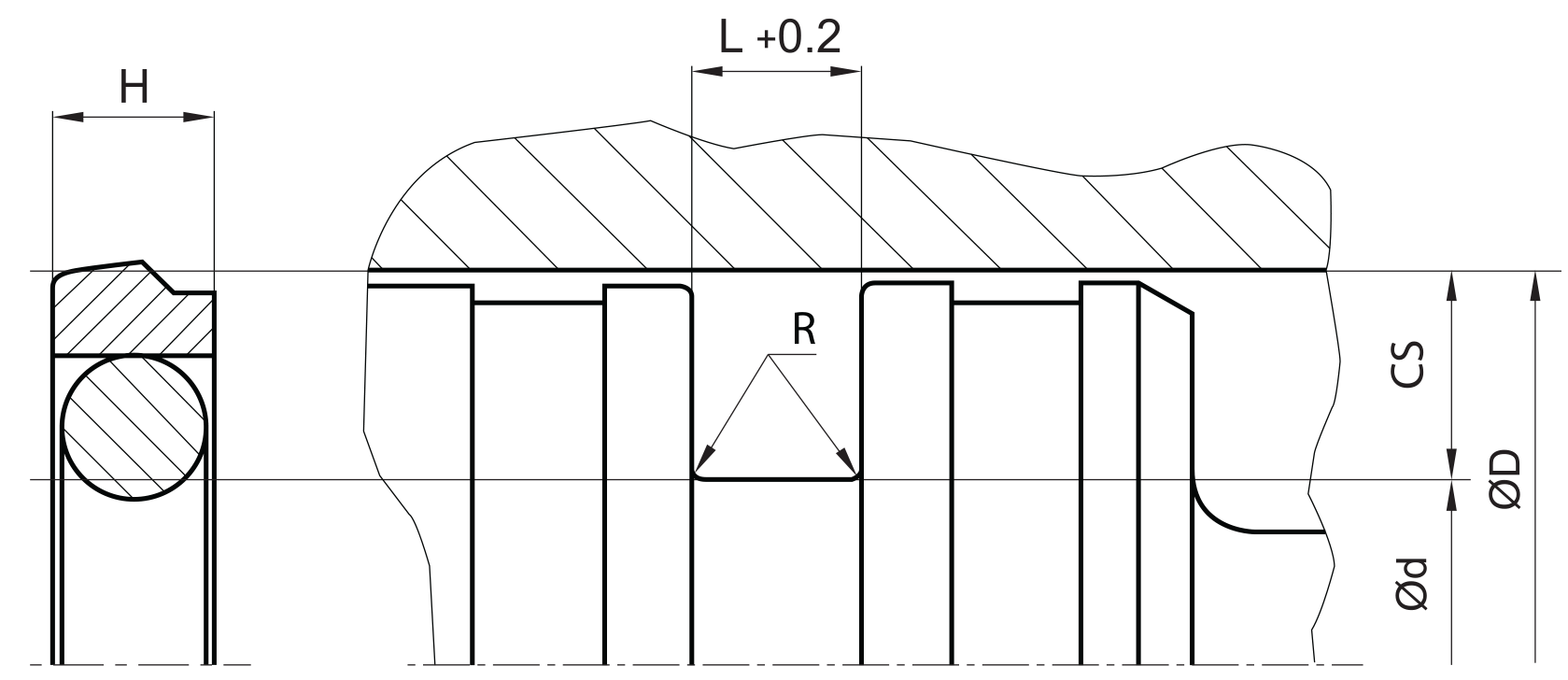
the ratio between nominal width and seal height should be in accordance to ISO 7425 part 1. we recommend the following values:
| ØD [mm] | ØD [mm] | L [mm] | cs = (ØD – Ød)/2 [mm] |
| 8 ~ 14,9 | ØD – 4,9 | 2,2 | 2.45 |
| 15 ~ 39,9 | ØD – 7,5 | 3.2 | 3.75 |
| 40 ~ 79,9 | ØD – 11 | 4.2 | 5.5 |
| 80 ~ 132,9 | ØD – 15,5 | 6.3 | 7.75 |
| 133 ~ 329,9 | ØD – 21 | 8.1 | 10.5 |
| 330 ~ 669,9 | ØD – 24,5 | 8.1 | 12.25 |
| 670 ~ 1000 | ØD – 28 | 9.5 | 14 |
| > 1000 | ØD – 28 | 9.5 | 14 |
| L | (ØD – Ød)/2 mm |
| 3.2 | 3.75 |
| 4.2 | 5.50 |
| 6.3 | 7.75 |
| 10.50 | 8.1 |
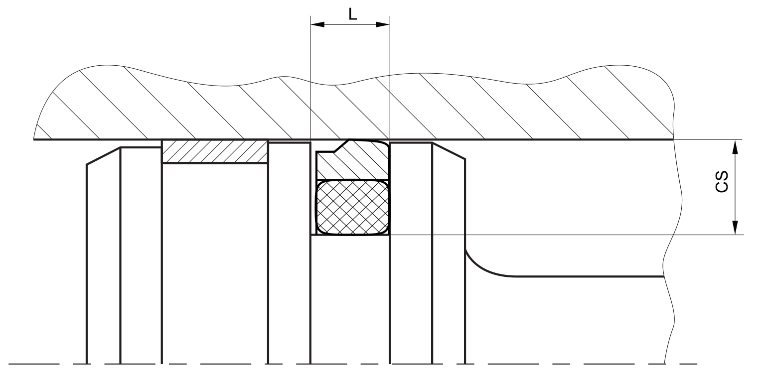
fitted:
don’t hesitate to contact our technical department for further information or for special requirements (temperature, speed etc.), so that suitable materi- als and/or designs can be recommended.