

description
simple cup seal, usually fixed on the piston by means of a clamping plate. mainly used for replacement in old hydraulic and pneumatic cylinders or for low-grade secondary applications. also used for food filling / portioning equipment.
- asymmetric single-acting piston lip seals.
- the profile is clamped at the flange, thereby ensuring stability and static sealingeffect.
- various materials are available for different purposes.
- sealing effect across a wide temperature range.
- radial inaccuracy or excentricity can be compensated by varying the length ofthe lip.
- for pressures up to 160 bar as a seal between pressurised space and atmosphere, pivoting and rotary movement and also long seal lips allow only lower values.
- design A with chamfer,design B with radius (depending on housing).
- suitable for long travel.
- seal lip length affects to“stick-slip” behavior.
- low break-awayload after prolonged periods of standstill.
- mainly used as a replacement in older pneumatic or hydraulic cylinders.
application
not bolded symbols; please consult our technical for application limitations
category of profile
machined or molded/standard/trade product.
single acting
the PS16 seal is designed for use as a piston seal – either single or double acting where two seals are used ‘back to back’
area of application: hydraulics
- reciprocating pistons in hydraulic and pneumatic cylinders,push rods and fittings.
- piston seal for applications with small extrusion gap and without special impact load.
- replacement for old leather seals.
- can also be used in rotating and pivoting applications at low loads (see also materials).
note
- special designed mounting space is required.
- complicated installation.
- do not use for new designs.
- housings with integrated radius on the non pressurised side (common for old leather seals) do not allow design A.
function
PS16 profiles are lip seals with clamp flange (also referred to as “cup seals”), designed to seal pressurised space against the at- mosphere or in case of back-to-back arrangement – to seal between two pressurised spaces. mainly for reciprocating movements, but also for minor rotating and pivoting movements. the design is based on application in standard hydraulic systems with conventional hydraulic oils, the use in pneumatic systems is quite common as well. the operating parameters are as defined in the sealing data sheet and material data. requirements deviating from these parameters can be met to a certain degree by changing the geometry in the software program.
operating parameters & material
| material | temperature | max. surface speed | max. pressure 1 | hydrolysis | dry running | wear resistance |
| PU | -30 °C … +110 °C | 0,5 m/s | 160 bar (16 MPa) | + | + | ++ |
| HPU | -20 °C … +110 °C | 0,5 m/s | 160 bar (16 MPa) | ++ | + | ++ |
| GPU | -30 °C … +110 °C | 0,5 m/s | 160 bar (16 MPa) | |||
| LTPU | -50 °C … +110 °C | 0,5 m/s | 160 bar (16 MPa) | – | + | ++ |
| SLPU | -20 °C … +110 °C | 0,5 m/s | 160 bar (16 MPa) | ++ | ++ | ++ |
| NBR | -30 °C … +100 °C | 0,5 m/s | 160 bar (16 MPa) | – | – | O |
| FKM | -20 °C … +200 °C | 0,5 m/s | 160 bar (16 MPa) | – | – | O |
| EPDM | -50 °C … +150 °C | 0,5 m/s | 160 bar (16 MPa) | ++ | – | O |
| HNBR | -25 °C … +150 °C | 0,5 m/s | 160 bar (16 MPa) | + | O | + |
the stated operation conditions represent general indications. it is recommended not to use all maximum values simultaneously. surface speed limits apply only to the presence of adequate lubrication film.
1 pressure ratings are dependent on the size of the extrusion gap.
2 attention: not suitable for mineral oils!
++ … particularly suitable o … conditional suitable
+ … suitable – … not suitable
for detailed information regarding chemical resistance please refer to our „list of resistance“. for increased chemical and thermal resistance rubber ma-
terials are to be preferred, Polyurethan materials increase wear resistance. for higher gliding speeds another system should be used (e.g. PTFE materials).
operating parameters for rotating applications
| PU | rubber | |
| maximum gliding speed [m/s] | 2 | 3 |
| maximum pressure [bar] | 7 | 5 |
these values are not valid for continous duty and strongly depending on the lip geometry. they are not to be used simultaneously. we also recommend contacting our technical department.
gap dimension
| operating pressure | cs = (ØD – Ød)/2 mm | |||||
| 4 | 5 | 7.5 | 10 | 10.5 | 15 | |
| max. permissible gap dimension | ||||||
| 50 bar (5 MPa) | 0.18 | 0.22 | 0.26 | 0.30 | 0.33 | 0.36 |
| 100 bar (10 MPa) | 0.16 | 0.18 | 0.24 | 0.27 | 0.31 | 0.35 |
| 160 bar (16 MPa) | 0.14 | 0.17 | 0.22 | 0.25 | 0.27 | 0.33 |
important note:
the above data are maximum value and can’t be used at the same time. e.g. the maximum operating speed depend on material type, pressure, tem- perature and gap value. temperature range also dependent on medium.
the table applies to an operating temperature of 70 °C.
surface quality
| surface roughness |
Rtmax (μm) |
Ra (μm) |
| sliding surface | ≤2,5 | ≤0,05-0,3 |
| bottom of groove | ≤6,3 | ≤1,6 |
| groove face | ≤15 | ≤3 |
tolerance recommendation
| seal housing | tolerances |
| Ød | h10 |
| Ød1 | h11 |
| ØD | H9 |
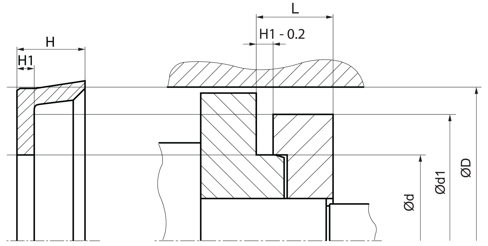
mode of installation
special shaped, open housings are required. the axial compression of the flange should not exceed 5 to 10% of the height , a clamping torque limitation should be arranged. to avoid twisting in the sealing lip, the compression should occur only at the clamp flange.
recommended mounting space:
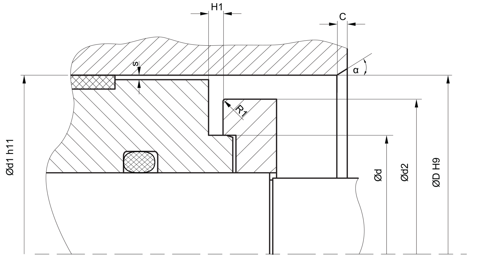
plastic guiderings (wearbands) have to feature a adequate cutting gap (recommendation: 2-5% of D). if metalic guides are used, spiral grooves shall be provided.
in order to avoid drag pressure built up in case of back-to-back arrangement, the distance between the seals should be as small as possible. radius R1 should be at least equal to the radius at the seal.
insertion chamfer:
in order to avoid damage to the piston seal during installation, the piston and the housing is to be chamfered and rounded as shown in the “recommended mounting space” drawing. the size of chamfer depends on the seal type and profile width.
| cs (mm) | c (mm) | |
| α = 15⁰ … 20⁰ | α = 20⁰ … 30⁰ | |
| 2.45 | 2.5 | 1.5 |
| 3.75 | 3.5 | 2 |
| 5.5 | 4.5 | 3 |
| 7.75 | 5 | 3.5 |
| 10.5 | 6 | 5 |
| 12.25 | 8 | 6 |
| 14 | 10 | 7 |
seal & housing recommendations
please note that we are able to produce those profiles to your specific need or any non standard housing. for detail measurements, please see Jet seal pars catalog…
this profile should only used as a replacement in already existing mounting spaces. use modern sealing systems for new designs.
fitted:
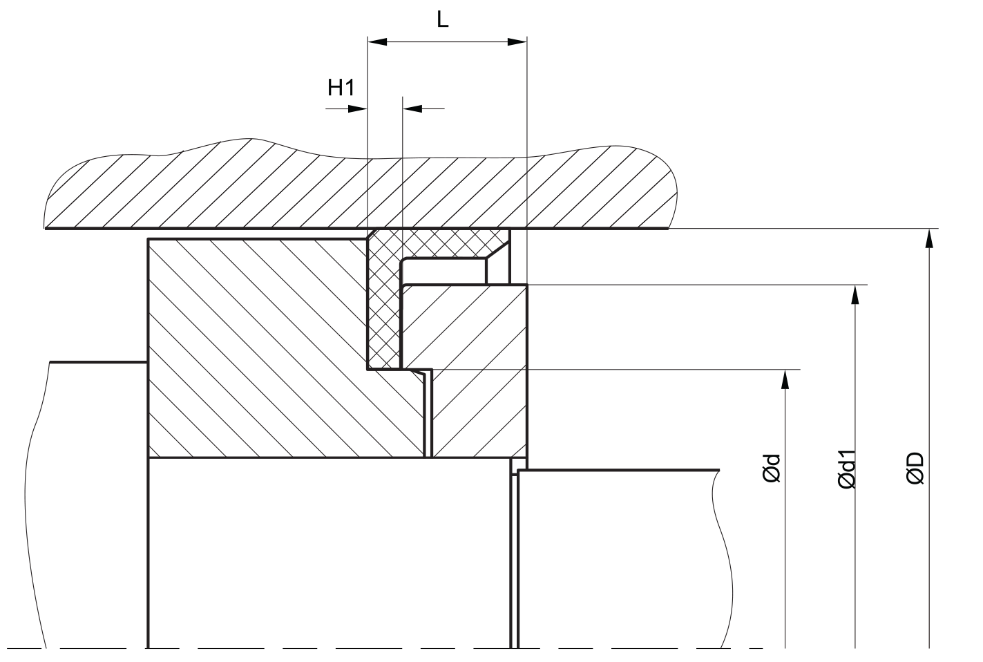
don’t hesitate to contact our technical department for further information or for special requirements (temperature, speed etc.), so that suitable materi- als and/or designs can be recommended.