

description
space saving, compact piston seal with integrated guiding elements excellent static sealing capacity, suitable for smallhousings.
- asymmetric double-acting compact piston seal set, consisting of a sealing part and combined guiding-and backup elements.
- interference fit on the inside diameter.
- various materials are available for different purposes.
- easy to slip over stepped grooves see notes on installation and recommended mounting space).
- high degree of sealing across a wide temperature range.
- for pressures up to 250 bar as a seal between pressurised spaces.
- excellent sealing in all pressure ranges.
- very good static and dynamic sealing.
- suitable for short and long travel.
- due to compact design an inexpensive construction of piston is possible.
- no drag pressure build-up.
- for holding functions.
- because of the excellent sealing effect,a fluid transport between the pressurised spaces is practically prevented.
- 1 groove on the inside diameter of the preload element for local limiting the preload force.
application
not bolded symbols; please consult our technical for application limitations
category of profile
machined or molded/standard/trade product.
double acting
the PS17-A seal is designed for use as a piston seal.
area of application: hydraulics
- reciprocating pistons in hydraulic cylinders.
- as piston seals for clamping function resp.for moderate requests for movement.
note
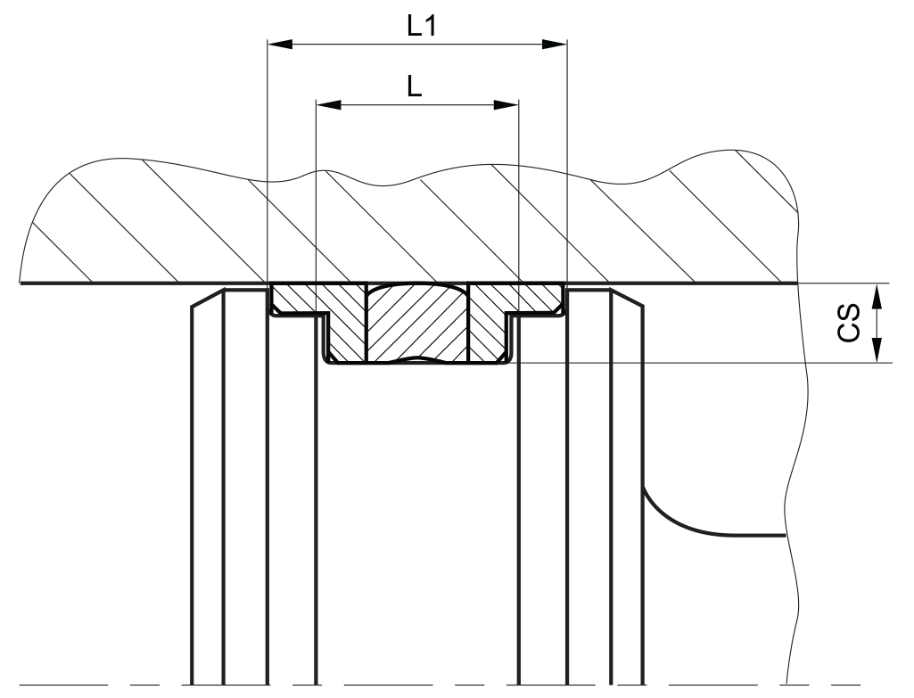
- the ratio between nominal width and sealing height cs/H should be approximately 1/2.
- for cross sections above 10 mm we recommend to use profile K09-N.
function
PS17-A profiles are compact piston seals designed to seal between two pressurised spaces; mainly for reciprocating movements. the design is based on application in standard hydraulic systems with conventional hydraulic oils.
the operating parameters are as defined in the sealing data sheet and material data. requirements deviating from these parameters can be met to a certain degree by changing the geometry in the software program.
operating parameters & material
| material | temperature | max. surface speed | max. pressure 1 | hydrolysis | dry running | wear resistance | |
| sealing element | back-up ring | ||||||
| PU | POM / PA | -30 °C … +100 °C | 0.5 m/s | 250 bar (25 MPa) | – | + | + |
| HPU | POM / PA | -20 °C … +100 °C | 0.5 m/s | 250 bar (25 MPa) | + | + | + |
| LTPU | POM / PA | -40 °C … +110 °C | 0.5 m/s | 250 bar (25 MPa) | – | + | + |
| SLPU | POM / PA | -20 °C … +100 °C | 0.7 m/s | 250 bar (25 MPa) | + | ++ | + |
| GPU | POM / PA | -30 °C … +100 °C | 0.5 m/s | 250 bar (25 MPa) | + | + | + |
the stated operation conditions represent general indications. it is recommended not to use all maximum values simultaneously. surface speed limits apply only to the presence of adequate lubrication film.
1 pressure ratings are dependent on the size of the extrusion gap.
2 POM up to ø260 mm, PA above ø260 mm
++ … particularly suitable o … conditional suitable
+ … suitable – … not suitable
for detailed information regarding chemical resistance please refer to our „list of resistance“. for increased chemical and thermal resistance rubber
materials are to be preferred, attention should be paid to restrictions for pressure range and wear resistance. for higher gliding speeds another system should be used (e.g. PTFE materials).
note on special materials:
the temperature limits are determined by the guide- and support parts, using special materials can expand the temperature limits.
gap dimension
by using the guide and support parts, the extrusion gap for the sealing part is already integrated in the seal. the gap between piston and housing should not exceed (D-d1)·0.13 resp. 1mm, fabrication tolerances have to be included.
surface quality
| surface roughness |
Rtmax (μm) |
Ra (μm) |
| sliding surface | ≤2,5 | ≤0,05-0,3 |
| bottom of groove | ≤6,3 | ≤1,6 |
| groove face | ≤15 | ≤3 |
tolerance recommendation
| seal housing | tolerances |
| Ød | h9 |
| ØD | H9 |
mode of installation
the first guiding- and backup element should be placed into the groove, then the sealing element should be slipped over the piston and snapped into the groove, then the second guiding- and backup element should be placed into the groove. for inside diameters of 40mm and more, the seal can generally be slipped over the piston and snapped into closed grooves. due to occuring deformation force at installation, as- sembly aid tools are to be used for large cross-sections. the material deformation should not exceed the value of 20%, otherwise the permanent deformation would be too large.
recommended mounting space:
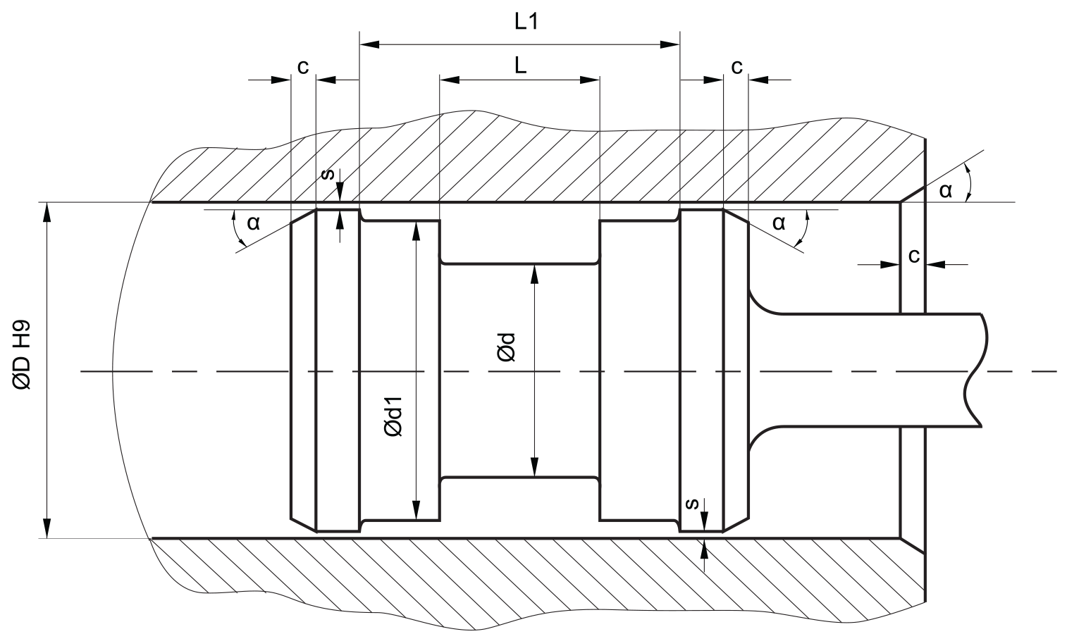
insertion chamfer:
in order to avoid damage to the piston seal during installation, the piston and the housing is to be chamfered and rounded as shown in the “rec- ommended mounting space” drawing. the size of chamfer depends on the seal type and profile width.
| cs (mm) | c (mm) | |
| α = 15⁰ … 20⁰ | α = 20⁰ … 30⁰ | |
| 4 | 3.5 | 2 |
| 5 | 4 | 2.5 |
| 6 | 4.5 | 3 |
| 7.5 | 5 | 4 |
| 10 | 6 | 5 |
| 12.5 | 8.5 | 6.5 |
| 15 | 10 | 7.5 |
| 20 | 13 | 10 |
instead of a chamfer, the piston can also be designed with a radius. recommended size of the radius is equal to size of chamfer (R=c).
seal & housing recommendations
please note that we are able to produce those profiles to your specific need or any non standard housing. for detail measurements, please see Jet seal pars catalog…
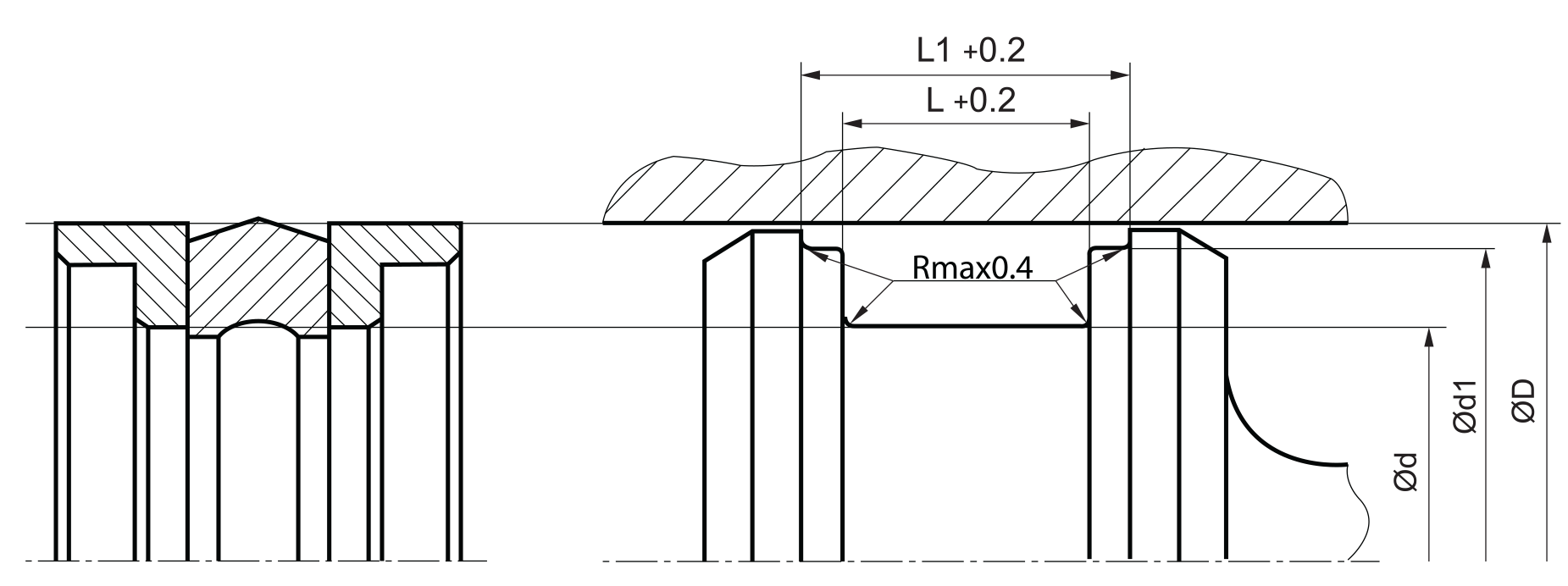
the ratio between nominal width and seal height cs/H should be approximately 1/2. therefore we recommend the following housing heights.
| ØD [mm] | Ød [mm] | L [mm] | cs = (ØD – Ød)/2 [mm] |
| 5 ~ 24,9 | ØD – 8 | 6 | 4 |
| 25 ~ 49,9 | ØD – 10 | 7 | 5 |
| 50 ~ 74,9 | ØD – 12 | 8 | 6 |
| 75 ~ 149,9 | ØD – 16 | 10 | 7.5 |
| 150 ~ 299,9 | ØD – 20 | 12 | 10 |
| 300 ~ 500 | ØD – 24 | 18 | 12.5 |
| 500 ~ 750 | ØD – 30 | 20 | 15 |
| > 750 | ØD – 40 | 26 | 20 |
we recommend to use K09-N for cross sections above 10 mm.
fitted:
don’t hesitate to contact our technical department for further information or for special requirements (temperature, speed etc.), so that suitable materi- als and/or designs can be recommended.