

description
finger-spring activated, asymmetrical PTFE piston seal, low friction and good dry run- ning properties, excellent chemical and thermal resistance, mainly used in chemical, pharma and food industry.
- asymmetric single acting piston lip seal, with the dynamic sealing lip being shorter than the static one. the preload is created by a finger spring inserted in the groove.
- interference fit on the inside diameter.
- various materials are available for different purposes.
- good sealing effect across a wide temperature range.
- sealing effect enhanced by high recovery rate.
- for pressures up to 200 bar as a seal between pressurised space and atmosphere(in certain cases even above, see “gap dimensions”).
- good sealing in all pressure ranges.
- excellent static and dynamic sealing after short run-in time.
- suitable for short and long travel.
- small break-awayload.
- no reverse leakage (i.e. minor relative motion of the sealing edges when thedirection is changed).
- little friction when dry running or when used in media with poor lubrication(conditionally suitable for use in aqueous media).
- flexible sealing lip due to large spring travel.
application
not bolded symbols; please consult our technical for application limitations
category of profile
machined or molded/standard/trade product.
single acting
the PS 19 seal is designed for use as a piston seal – either single or double acting where two seals are used ‘back to back’
area of application: hydraulics
reciprocating and swiveling pistons in cylinders, push rods, fittings in the chemical industry.
note
- special measures required when used at temperatures below -60°C, because of material shrinkage.
- considering the limited long-time rupture strength of PTFE materials, the cs/H ratio should not fall below a value of 1/1.5.
- cross-sections limited to 10 mm.
- varying the angle of the chamfer on the dynamic sealing lip allows adaptation to media (steeper angle for high viscosity media) respec-
tively a pressure relief (flat angle).
function
PS 19 profiles are lip seals designed to seal pressurised space against the atmosphere or -in case of back to back arrangement with interme- diate guidering – to seal between two pressurised spaces, mainly for reciprocating movements. the design is based on application in aggres- sive media or with high thermal demands. the operating parameters are as defined in the sealing data sheet and material data. requirements deviating from these parameters can be met to a certain degree by changing the geometry in the software program.
operating parameters & material
| material | temperature | max. surface speed | max. pressure 1 | hydrolysis | dry running | wear resistance | |
| sealing element | spring | ||||||
| PTFE | 14.310 | -200 °C … +260 °C | 15 m/s | 100 bar (10 MPa) | ++ | ++ | + |
| PTFE glass | 14.310 | -200 °C … +260 °C | 15 m/s | 160 bar (16 MPa) | ++ | ++ | + |
| PTFE bronze | 14.310 | -200 °C … +260 °C | 15 m/s | 160 bar (16 MPa) | ++ | ++ | + |
| UHMWPE | 14.310 | -200 °C … +260 °C | 15 m/s | 200 bar (20 MPa) | ++ | + | + |
the stated operation conditions represent general indications. it is recommended not to use all maximum values simultaneously. surface speed limits apply only to the presence of adequate lubrication film.
1 pressure ratings are dependent on the size of the extrusion gap.
++ … particularly suitable o … conditional suitable
+ … suitable – … not suitable
for detailed information regarding chemical resistance please refer to our “list of resistance”. for decreased leackage rates elastomer materials (polyure-
thane or rubber) in other sealing systems are to be preferred.
gap dimension
important note:
the above data are maximum value and can’t be used at the same time. e.g. the maximum operating speed depend on material type, pressure, tem- perature and gap value. temperature range also dependent on medium.
the table refers to a operating temperature of 80°C. temperatures below may increase the safe extrusion gap slightly, at temperatures above
80 °C, the gap dimensions has to be reduced or a stronger profile selected. in exceptional cases, a pressure above the limit of 200 bar is possible,
the safe extrusion gap is the result of the tolerance pair H8/f8, influences due to thermal expansion have to be considered. we also recommend
contacting our technical department.
surface quality
| surface roughness |
Rtmax (μm) |
Ra (μm) |
| sliding surface | ≤2,5 | ≤0,05-0,3 |
| bottom of groove | ≤6,3 | ≤1,6 |
| groove face | ≤15 | ≤3 |
tolerance recommendation
| seal housing | tolerances |
| Ød | h10 |
| ØD | H9 |
mode of installation
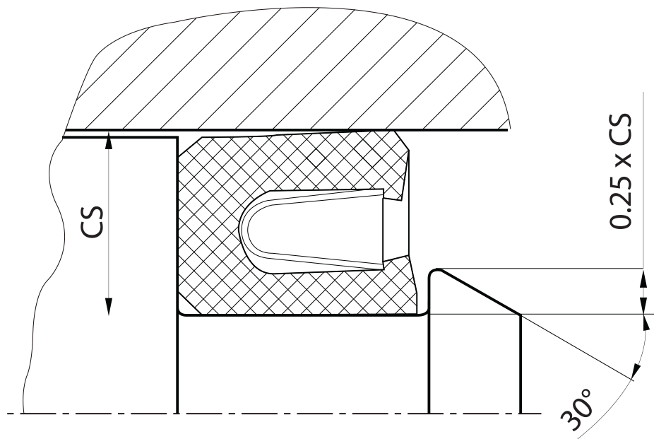
normally a open housing should be designed. the profile should not be snaped in, the spring may be damaged and a faultless function can not be ensured. in special cases a snap-in installation is possible, therefore the housing has to be designed accordingly. the seal can only be held by a retaining housing step, having a width of 0.25·CS and a distinctive 30° chamfer, all edges must be rounded. the smallest possible diameter for such a snap-in installation is 10·CS.
recommended mounting space:
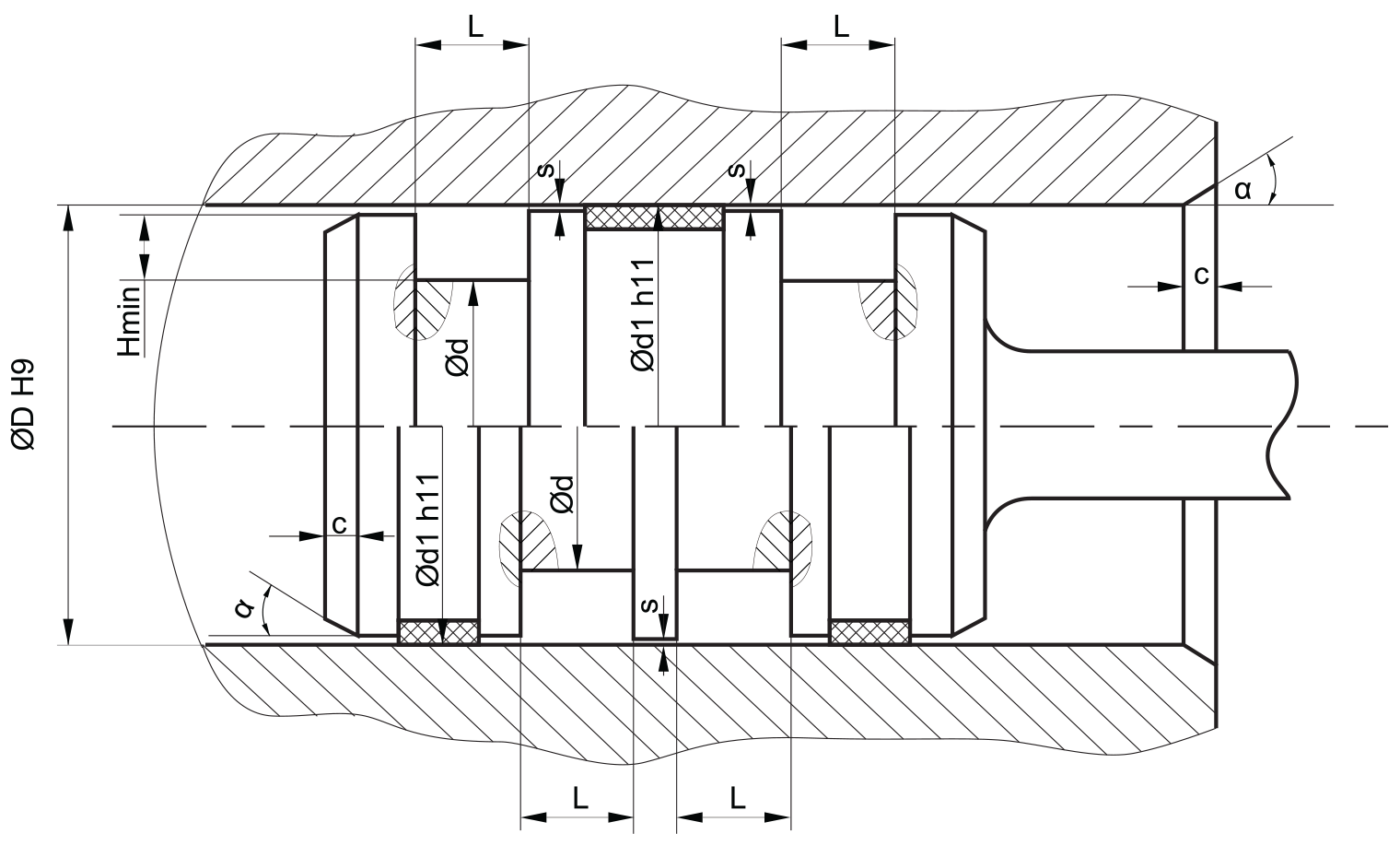
plastic guiderings (wearbands) have to feature a adequate cutting gap (recommendation: 2-5% of D). if metalic guides are used, spiral grooves shall be provided. small values for Hmin allow slipping the seal over the piston, but the height of the retaining collar has to be sufficient to assure a stable fit in the housing (see “mode of installation”). in order to avoid drag pressure built up in case of back-to-back arrangement, the distance between the seals should be as small as possible.
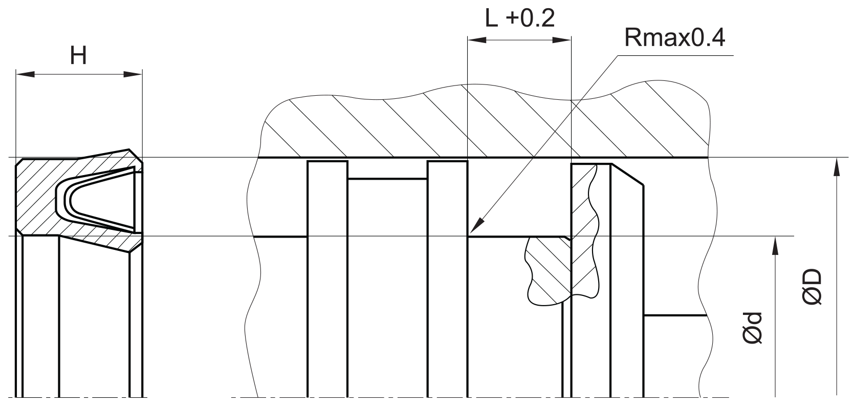
insertion chamfer:
in order to avoid damage to the piston seal during installation, the piston and the housing is to be chamfered and rounded as shown in the “recommended mounting space” drawing. the size of chamfer depends on the seal type and profile width.
| cs (mm) | c (mm) | |
| α = 15⁰ … 20⁰ | α = 20⁰ … 30⁰ | |
| 4 | 3.5 | 2 |
| 5 | 4 | 2.5 |
| 6 | 4.5 | 3 |
| 7.5 | 5 | 4 |
| 10 | 6 | 5 |
| 12.5 | 8.5 | 6.5 |
| 15 | 10 | 7.5 |
| 20 | 13 | 10 |
instead of a chamfer, the piston can also be designed with a radius. recommended size of the radius is equal to size of chamfer (R=c).
seal & housing recommendations
please note that we are able to produce those profiles to your specific need or any non standard housing. for detail measurements, please see Jet seal pars catalog…
with PTFE materials, the profile size does not so much depend on the seal diameter but rather on pressure and extrusion gap. this relationship is described under “gap dimensions”. nominal widths not shown in the diagram can be interpolated.
| cs = (ØD – Ød)/2 [mm] | tolerances |
| 2 | 3.5 |
| 3 | 5.1 |
| 4 | 6.5 |
| 5 | 8.8 |
| 10.2 | 6 |
| 12.8 | 7.5 |
| 17 | 10 |
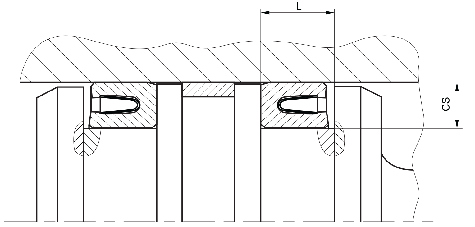
fitted:
don’t hesitate to contact our technical department for further information or for special requirements (temperature, speed etc.), so that suitable materi- als and/or designs can be recommended.
the ratio between nominal width and seal height cs/H should not drop below 1/1.5. therefore we recommend the following housing heights.