

description
asymmetric rod seal for standard applications. interference fit on outside diameter maintains stable fit in the housing. design provides ultimate sealing effect over a
wide temperatur range and good backpumping ability. also used as secondary seal in combination with PTFE-seal type RS08.
- asymmetric single-acting rod lipseals, with the dynamic sealing lip being shorter than the static one.
- interference fit on the outside diameter.
- various materials are available for different purposes.
- snaps into simple grooves (see notes on installation).
- best sealing effect across a wide temperature range.
- sealing effect enhanced by high recovery rate.
- for pressures up to 400 bar as a seal between pressurised space and atmosphere.
- good sealing in the low pressure range.
- excellent static and dynamic sealing.
- suitable for long travel.
- little inclination to“stick-slip”.
- low break-away load after prolonged periods of standstill.
application

not bolded symbols; please consult our technical for application limitations
category of profile
machined or molded/standard/trade product.
single acting
the RS 0 1 seal is designed for use as a rod seal.
area of application: hydraulics
- reciprocating rods on hydraulic cylinders,push rods and fittings.
- rod for applications seals with small extrusion gap and without special impact load.
- if composite seals on PTFE basis are used,this rod seal can be used as a secondary seal.
- can also be used as a pivot seal at low loads.
note
- this seal has the correct functioning dimension only when mounted. when slipping the seal over the piston rod, it may appear too large.
- the ratio between nominal width and sealing height cs/H should not drop below a value of 1/1.25 (essentially according to ISO 5597 housings for piston and rod seals).
function
RS 0 1 profiles are lip seals designed to seal pressurised space against the atmosphere; mainly for reciprocating movements. the design is based on application in standard hydraulic systems with conventional hydraulic oils. the operating parameters are as defined in the seal- ing data sheet and material data. requirements deviating from these parameters can be met to a certain degree by changing the geom- etry in the software program
| sealing element | temperature(°C) | max. surface speed | max. pressure | hydrolysis | dry running | wear resistance |
| PU | -30 … +110 | 0,5 m/s | 400 bar (40 MPa) | – | + | ++ |
| HPU | -20 … +125 | 0,5 m/s | 400 bar (40 MPa) | ++ | + | ++ |
| LTPU | -50 … +110 | 0,5 m/s | 400 bar (40 MPa) | – | + | ++ |
| SPU | -20 … +110 | 0,7 m/s | 400 bar (40 MPa) | ++ | ++ | ++ |
| CPU | -30 … +110 | 0,5 m/s | 400 bar (40 MPa) | ++ | + | ++ |
for detailed information regarding chemical resistance please refer to our „list of resistance“. for increased chemical and thermal resistance rubber
materials are to be preferred, attention should be paid to restrictions for pressure range and wear resistance. for higher gliding speeds another system should be used (e.g. PTFE materials).
gap dimension:
| operating pressure | cs = (ØD – Ød)/2 mm | |||||
| 4 | 5 | 7.5 | 10 | 12.5 | 15 | |
| safe extrusion gap (mm) | ||||||
| 100 bar (10 MPa) | 0.18 | 0.22 | 0.32 | 0.38 | 0.45 | 0.53 |
| 200 bar (20 MPa) | 0.12 | 0.16 | 0.25 | 0.33 | 0.40 | 0.45 |
| 300 bar (30 MPa) | 0.07 | 0.13 | 0.21 | 0.28 | 0.36 | 0.42 |
| 400 bar (40 MPa) | 0.05 | 0.10 | 0.19 | 0.26 | 0.33 | 0.39 |
important note:
the above data are maximum value and can’t be used at the same time. e.g. the maximum operating speed depend on material type, pressure, tem- perature and gap value. temperature range also dependent on medium.
the table applies to an operating temperature of 70 °C.
use larger cross sections to increase maximum allowed gap dimension. if the permissible extrusion gap cannot be achieved, RS 01 is to be used.
surface quality
| surface roughness |
Rtmax (μm) |
Ra (μm) |
| sliding surface | ≤2,5 | ≤0,1-0,5 |
| bottom of groove | ≤6,3 | ≤1,6 |
| groove face | ≤15 | ≤3 |
tolerance recommendation
| seal housing | tolerances |
| Ød | f8 |
| ØD | H10 |
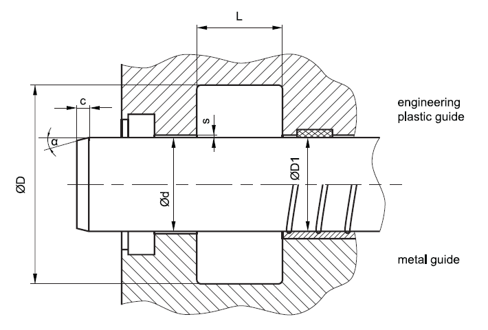
mode of installation
for inside diameters of 25mm or more, and dependant on radial cross section (cs), seals may be snapped into closed housings.
| Ød | type of installation |
| ≤ 6•cs | open mounting space required |
| > 6•cs …..≤ 10•cs | snap mounting with tool |
| > 10•cs | snap mounting by hand |
recommended guide tolerance D1:
| d f8 [mm] |
p ≤ 100 [bar] |
100 < p ≤ 200 [bar] |
p > 200 [bar] |
secondary seal |
| ≤ 100 | H10 | H8 | H8 | H8 |
| > 100 ≤ 200 | H10 | H8 | H7 | H8 |
| >200 | H9 | H8 | H7 | H8 |
insertion chamfer:
in order to avoid damage to the rod seal during installation, the piston rod is to be chamfered and rounded as shown in the “recommended mounting space” drawing. the size of chamfer depends on the seal type and profile width.
| cs (mm) | c (mm) | |
| α = 15⁰ … 20⁰ | α = 20⁰ … 30⁰ | |
| (2) | 2 | 1 |
| (3) | 3 | 1.5 |
| 4 | 3.5 | 2 |
| 5 | 4 | 2.5 |
| 6 | 4.5 | 3 |
| 7.5 | 5 | 4 |
| 10 | 6 | 5 |
| 12.5 | 8.5 | 6.5 |
| 15 | 10 | 7.5 |
| 20 | 13 | 10 |
seal & housing recommendations
please note that we are able to produce those profiles to your specific need or any non standard housing. for detail measurements, please see Jet seal pars catalog…
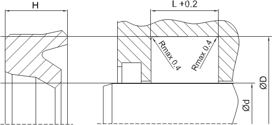
the ratio between nominal width and seal height cs/H should not drop below 1/1,25. therefore we recommend the following housing heights.
| Ød [mm] | ØD [mm] | L [mm] | cs = (ØD – Ød)/2 [mm] |
| 5 ~ 24,9 | ød + 8 | 6.3 | 4 |
| 25 ~ 49,9 | ød + 10 | 8 | 5 |
| 50 ~ 149,9 | ød + 15 | 10 | 7.5 |
| 150 ~ 299,9 | ød + 20 | 14 | 10 |
| 300 ~ 499,9 | ød + 25 | 17 | 12.5 |
| 500 ~ 699,9 | ød + 30 | 25 | 15 |
| 700 ~ 1000 | ød + 40 | 32 | 20 |
| > 1000 | ød + 40 | 32 | 20 |
fitted
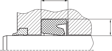
don’t hesitate to contact our technical department for further information or for special requirements (temperature, speed etc.), so that suitable materi- als and/or designs can be recommended.