

description
O-Ring activated, asymmetrical rod seal. interference fit on outside diameter maintains stable fit in the housing. design provides ultimate sealing effect. especially suitable for short stroke applications (e.g. spindle seals, couplingactuators…).
- asymmetric single-acting rod lip seals, with the dynamic sealing lip being shorter than the static one. in addition, an O-ring inserted into the groove increases the preload.
- interference fit on the outside diameter.
- various materials are available for different purposes.
- snaps into simple grooves (see notes on installation).
- best sealing effect across a wide temperature range.
- sealing effect enhanced by high recovery rate.
- for pressures up to 400 bar as a seal between pressurised space and atmosphere.
- good sealing in all pressure ranges.
- excellent static and dynamic sealing
- suitable for short travel.
- no reverse leakage (i.e. minor relative motion of the sealing edges when the direction is changed).
- recommended when holding or positioning under pressure.
application

not bolded symbols; please consult our technical for application limitations
category of profile
machined only.
single acting
the RS03 seal is designed for use as a rod seal.
area of application: hydraulics
- reciprocating rods on hydraulic cylinders,push rods, fittings.
- as rod seals for switching functions (e.g.clutch operation).
- as rod seals for clamping functions.
- when an appropriate preload element is used,also suitable for low temperatures (down to -50°C).
note
- this seal has the correct functioning dimension only when mounted. when slipping the seal over the piston rod, it may appear too large.
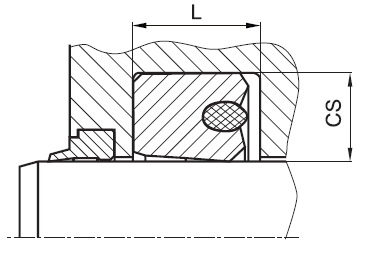
- the ratio between nominal width and sealing height cs/H should not drop below a value of 1/1.25 (essentially according to ISO 5597 housings for piston and rod seals).
- high degree of friction.
- high break-awaymoment.
- the recovery volume is smaller than with simple lip seals.
- cross-section limited to 20 mm.
function
RS03 profiles are lip seals designed to seal pressurised space against the atmosphere; mainly for reciprocating movements. the designis based on application in standard hydraulic systems with conventional hydraulic oils. the operating parameters are as defined in thesealing data sheet and material data. requirements deviating from these parameters can be met to a certain degree by changing the geometry in the software program.
for detailed information regarding chemical resistance please refer to our „list of resistance“. for increased chemical and thermal resistance rubber
materials are to be preferred, attention should be paid to restrictions for pressure range and wear resistance. for higher gliding speeds another system should be used (e.g. PTFE materials).
note on special materials:
other materials such as Viton, Silicone, EPDM, H-NBR, etc., can be used for the preload element, but they are only useful in specific cases (temperature or
chemical influences).
gap dimension
| operating pressure | cs = (ØD – Ød)/2 mm | |||||
| 4 | 5 | 7.5 | 10 | 12.5 | 15 | |
| safe extrusion gap (mm) | ||||||
| 100 bar (10 MPa) | 0.18 | 0.22 | 0.32 | 0.40 | 0.45 | 0.55 |
| 200 bar (20 MPa) | 0.12 | 0.15 | 0.25 | 0.33 | 0.40 | 0.45 |
| 300 bar (30 MPa) | 0.07 | 0.12 | 0.22 | 0.30 | 0.37 | 0.42 |
| 400 bar (40 MPa) | 0.05 | 0.10 | 0.18 | 0.25 | 0.34 | 0.40 |
surface quality
| surface roughness |
Rtmax (μm) |
Ra (μm) |
| sliding surface | ≤2,5 | ≤0,1-0,5 |
| bottom of groove | ≤6,3 | ≤1,6 |
| groove face | ≤15 | ≤3 |
tolerance recommendation
| seal housing | tolerances |
| Ød | f8 |
| ØD | H10 |
mode of installation
| Ød | type of installation |
| ≤ 6•cs | open mounting space required |
| > 6•cs …..≤ 10•cs | snap mounting with tool |
| > 10•cs | snap mounting by hand |
recommended mounting space:
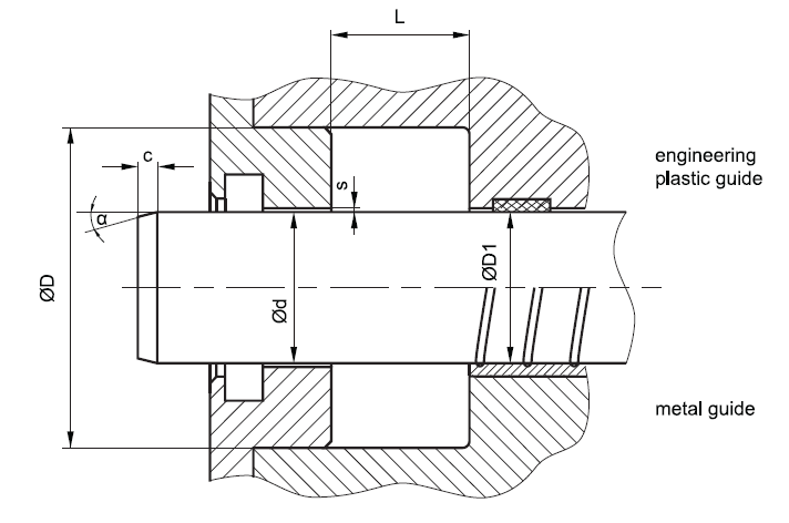
recommended guide tolerance D1:
| d f8 [mm] |
p ≤ 100 [bar] |
100 < p ≤ 200 [bar] |
p > 200 [bar] |
secondary seal |
| ≤ 100 | H10 | H8 | H8 | H8 |
| > 100 ≤ 200 | H10 | H8 | H7 | H8 |
| >200 | H9 | H8 | H7 | H8 |
insertion chamfer:
in order to avoid damage to the rod seal during installation, the piston rod is to be chamfered and rounded as shown in the “recommended mounting space” drawing. the size of chamfer depends on the seal type and profile width.
| cs (mm) | c (mm) | |
| α = 15⁰ … 20⁰ | α = 20⁰ … 30⁰ | |
| (2) | 2 | 1 |
| (3) | 3 | 1.5 |
| 4 | 3.5 | 2 |
| 5 | 4 | 2.5 |
| 6 | 4.5 | 3 |
| 7.5 | 5 | 4 |
| 10 | 6 | 5 |
| 12.5 | 8.5 | 6.5 |
| 15 | 10 | 7.5 |
| 20 | 13 | 10 |
seal & housing recommendations
please note that we are able to produce those profiles to your specific need or any non standard housing. for detail measurements, please see Jet seal pars catalog…
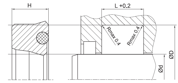
the ratio between nominal width and seal height cs/H should not drop below 1/1,25. therefore we recommend the following housing heights
| Ød [mm] | ØD [mm] | L [mm] | cs = (ØD – Ød)/2 [mm] |
| 5 ~ 24,9 | ød + 8 | 6.3 | 4 |
| 25 ~ 49,9 | ød + 10 | 8 | 5 |
| 50 ~ 149,9 | ød + 15 | 10 | 7.5 |
| 150 ~ 299,9 | ød + 20 | 14 | 10 |
| 300 ~ 499,9 | ød + 25 | 17 | 12.5 |
| 500 ~ 699,9 | ød + 30 | 25 | 15 |
| 700 ~ 1000 | ød + 40 | 32 | 20 |
| > 1000 | ød + 40 | 32 | 20 |
fitted:
don’t hesitate to contact our technical department for further information or for special requirements (temperature, speed etc.), so that suitable materi- als and/or designs can be recommended.