

description
O-Ring activated asymmetric PTFE rod seal, low friction. in tandem design together with double acting wipers for extreme low or high speed or positioning functions. as primary seal in combination with secondary RS01 seal with good resistance to pres- sure shocks used in mobile hydraulics, machine tools, injection moulding machines, heavy hydraulics.
- asymmetric single-acting composite rod seals, with a gliding part made of low friction material and an elastic preload element.
- interference fit on the outside diameter.
- various materials are available for different purposes.
- mostly used in a sealing system, either in tandem arrangement with double wip-er
- snaps into simple grooves (see notes on installation).
- the free space on the trailing side reduces the risk of gap extrusion.
- highest degree of sealing across a wide temperature range.
- sealing effect enhanced by high recovery.
- for pressures up to 400 bar (in special cases up to 800 bar) as a seal between pres-surised space and atmosphere.
- good sealing in all pressure ranges.
- good static and dynamic sealing.
- suitable for short and long travel with extremely slow or quick movements.
- no stick-slip.
- small break-awayload after prolonged periods of standstill.
- exact positioning due to little friction.
- high mechanical efficiency.
- insensitive to thermal damage caused by air in the oil.
application

category of profile
machined or molded/standard/trade product.
single acting
the RS 09-B seal is designed for use as a rod seal.
area of application: hydraulics
- reciprocating rods on hydraulic cylinders,small swiveling motion permissible.
- as rod seal in tandem arrangement for positioning tasks for machine tools and robots.
- as rod seal in combination with lip seals as secondary seal for rough operations (e.g.construction machines, heavy machinery).
- for heavy-dutyoperating conditions, profile S09-ES is preferred.
- dimensions according to ISO 7425 part 2 are common, as well as standard types that differ slightly in the depth of the mounting
space. for specific dimensions see “range of profile sizes”.
note
- the calculation program is based on mounting spaces according to ISO 7425, part 2. intermediate sizes are possible, with an O-ring for standard sizes. for deviating dimensions, use S09-ES. attention must be given to a balanced ratio between sealing part and preload element.
- there should be enough space for trailing oil.
- the recovery capacity depends on the sealing system.
function
RS 09-B profiles are composite rod seals designed to seal pressurised space against the atmosphere; mainly for reciprocating movements.
the design is based on application in standard hydraulic systems with conventional hydraulic oils. the operating parameters are as defined
in the sealing data sheet and material data. requirements deviating from these parameters can be met to a certain degree by changing the
geometry in the software program.
operating parameters & material
| sealing element | energizer | temperature °C | max-surface speed | max-pressure | hydrolysis | dry running | wear resistance |
| PTFE glas | NBR 70 SH-A | -30 °C … +100 | 10 m/s | 400 bar (40 MPa)
800 bar (80 MPa)3 |
– | ++ | + |
| PTFE bronze | NBR 70 SH-A | -30 °C … +100 | 10 m/s | – | ++ | + | |
| PTFE carbon | NBR 70 SH-A | -30 °C … +100 | 10 m/s | – | ++ | + | |
| PTFE glass | NBR 75 SH-A | -20 °C … +200 | 10 m/s | – | ++ | + | |
| PTFE bronze | NBR 75 SH-A | -20 °C … +200 | 10 m/s | – | ++ | + | |
| PTFE carbon | NBR 75 SH-A | -20 °C … +200 | 10 m/s | – | ++ | + | |
| PTFE glass | EPDM 70 SH-A | -50 °C … +150 | 10 m/s | ++ | ++ | + | |
| PTFE bronze | EPDM 70 SH-A | -50 °C … +150 | 10 m/s | ++ | ++ | + | |
| PTFE carbon | EPDM 70 SH-A | -50 °C … +150 | 10 m/s | ++ | ++ | + | |
| PTFE glass | MVQ 70 SH-A | -60 °C … +200 | 10 m/s | ++ | ++ | + | |
| PTFE bronze | MVQ 70 SH-A | -60 °C … +200 | 10 m/s | ++ | ++ | + | |
| PTFE carbon | MVQ 70 SH-A | -60 °C … +200 | 10 m/s | ++ | ++ | + | |
| UHMWPE | MVQ 70 SH-A | -60 °C … +80 | 10 m/s | 400 bar (40 MPa) | ++ | ++ | + |
| HPU D57 | NBR 70 SH-A | -30 °C … +110 | 5 m/s | 600 bar (40 MPa) | ++ | + | + |
the stated operation conditions represent general indications. it is recommended not to use all maximum values simultaneously. surface speed limits apply only to the presence of adequate lubrication film.
1 pressure ratings are dependent on the size of the extrusion gap.
2 attention: not suitable for mineral oils!
3 only in special cases (small extrusion gap, low surface speed).
++ … particularly suitable o … conditional suitable
+ … suitable – … not suitable
for detailed information regarding chemical resistance please refer to our “list of resistance”. for decreased leackage rates elastomer materials (polyure-
thane or rubber) in other sealing systems are to be preferred.
note on special materials:
as temperature limit and chemical resistance are determined by the preload element, the temperature range can be increased and the resis-
tance to chemical influences improved, if a special material is used for the preload element.
gap dimension
| operating pressure | cs = (ØD – Ød)/2 mm | ||||||
| 2.45 | 3.65 | 5.35 | 7.55 | 10.25 | 12 | 13.65 | |
| safe extrusion gap (mm) | |||||||
| 100 bar (10 MPa) | 0.27 | 0.33 | 0.38 | 0.43 | 0.50 | 0.55 | 0.60 |
| 200 bar (20 MPa) | 0.19 | 0.16 | 0.25 | 0.28 | 0.33 | 0.37 | 0.45 |
| 300 bar (30 MPa) | 0.17 | 0.20 | 0.22 | 0.25 | 0.30 | 0.34 | 0.38 |
| 400 bar (40 MPa) | 0.16 | 0.18 | 0.19 | 0.21 | 0.25 | 0.28 | 0.30 |
important note:
the above data are maximum values and cannot be used at the same time. e.g. the maximum operating speed depends on material type, pressure, temperature and gap value. temperature range also dependent on medium”
the table refers to a operating temperature of 80°C. temperatures below may increase the safe extrusion gap slightly, at temperatures above
80 °C, the gap dimensions has to be reduced or a stronger profile selected.
for extrusion gap sizes resulting from tolerance pair H8/f8 pressure ranges above 400 bar can be reached in special cases, influences due to
thermal expansion have to be considered. we recommend to contact our technical department.
surface quality
| surface roughness |
Rtmax (μm) |
Ra (μm) |
| sliding surface | ≤2,5 | ≤0,1-0,5 |
| bottom of groove | ≤6,3 | ≤1,6 |
| groove face | ≤15 | ≤3 |
tolerance recommendation
| seal housing | tolerances |
| Ød | f8 |
| ØD | H10 |
mode of installation
for inside diameters of 25 mm or more, and dependant on radial cross section (cs), seals may be snapped into a closed housing.
| Ød | type of installation |
| ≤ 6•cs | open mounting space required |
| > 6•cs …..≤ 10•cs | snap mounting with tool |
| > 10•cs | snap mounting by hand |
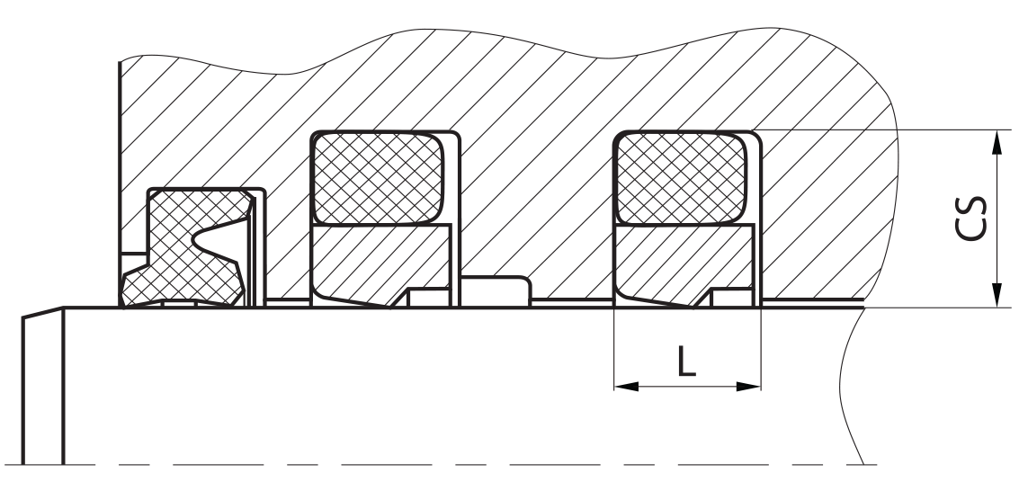
recommended mounting space:
two types of mounting space are recommended depending on application:
|
secondary seal |
wiper |
|
| version 1 | RS 09-B
RS 09-A |
WR 11
WR 12 WR 13 WR14 WR15 |
| version 2 | RS01 and all U-ring Types | all type possible |
the choice of the sealing system does not depend on the guide elements.
recommended guide tolerance D1:
in most cases the guiding elements are integrated in the piston seal system on both sides. if not use below recommendations for D1 (=inside diameter of the guiding elements):
| d f8 [mm] | p ≤ 100 [bar] | 100 < p ≤ 200 [bar] | p > 200 [bar] |
| ≤ 100 | H10 | H8 | H8 |
| > 100 ≤ 200 | H10 | H8 | H7 |
| >200 | H9 | H8 | H7 |
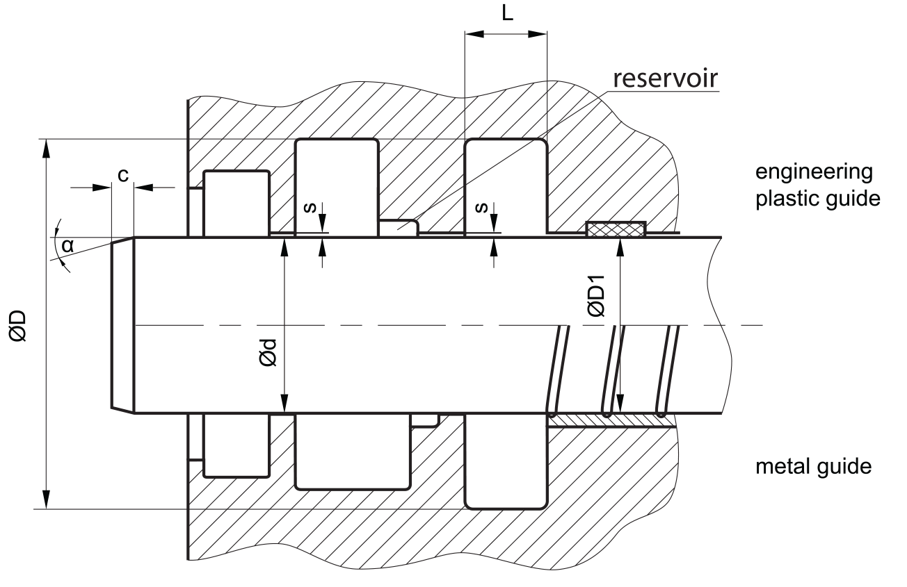
insertion chamfer:
in order to avoid damage to the rod seal during installation, the piston rod is to be chamfered and rounded as shown in the “recommended mounting space” drawing. the size of chamfer depends on the seal type and profile width.
| cs (mm) | c (mm) | |
| α = 15⁰ … 20⁰ | α = 20⁰ … 30⁰ | |
| 2.45 | 2.5 | 1.5 |
| 3.5 | 3.5 | 2 |
| 5.35 | 4.5 | 3 |
| 7.55 | 5 | 3.5 |
| 10.25 | 6 | 5 |
| 12 | 8 | 6 |
| 13.65 | 10 | 7 |
seal & housing recommendations
please note that we are able to produce those profiles to your specific need or any non standard housing. for detail measurements, please see Jet seal pars catalog…
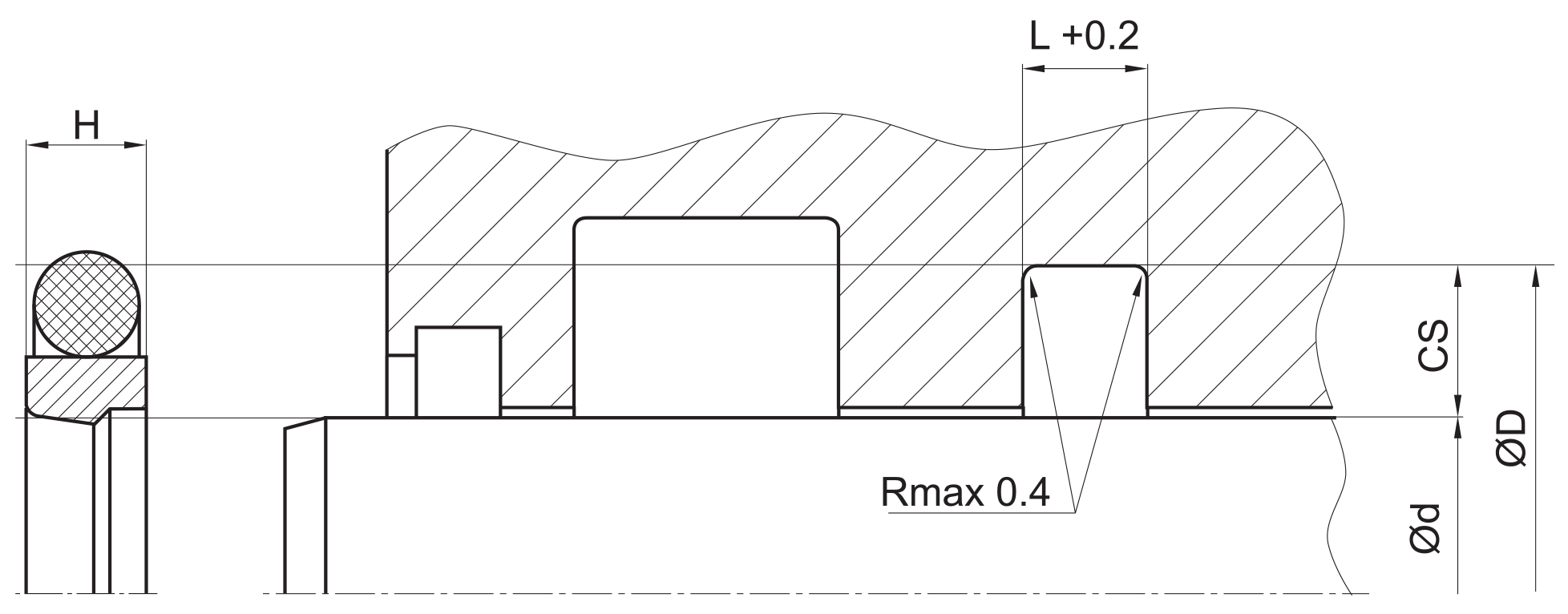
the ratio between nominal width and seal height should be in accordance to ISO 7425 part 1. we recommend the following values:
| Ød [mm] | ØD [mm] | L [mm] | cs = (ØD – Ød)/2 [mm] |
| 5 ~ 7,9 | Ød + 4,9 | 2.2 | 2.45 |
| 8 ~ 18,9 | Ød + 7,3 | 3.2 | 3.65 |
| 19 ~ 37,9 | Ød + 10,7 | 4.2 | 5.35 |
| 38 ~ 199,9 | Ød + 15,1 | 6.3 | 7.55 |
| 200 ~ 255,9 | Ød + 20,5 | 8.1 | 10.25 |
| 256 ~ 649,9 | Ød + 24 | 8.1 | 12 |
| 650 ~ 1.000 | Ød + 27,3 | 9.5 | 13.65 |
| > 1.000 | Ød + 27,3 | 9.5 | 13.65 |
in case of large deviations of L use RS09-B.
fitted:
don’t hesitate to contact our technical department for further information or for special requirements (temperature, speed etc.), so that suitable materi- als and/or designs can be recommended.