

description
O-Ring activated asymmetric PU rod seal with excellent dynamic sealing capacity. used secondary seal in tandem design (together with primary S09-B) to minimize residual oil film. for mobile hydraulics, injection moulding machines, heavy hydraulics.
- asymmetric single acting composite rod seals, with a gliding part made of excel- lent wear resistant polyurethane and an elastic preload element.
- interference fit on the outside diameter.
- various materials are available for different purposes.
- mostly used in a sealing system as secondary seal in combination with a PTFEgliding part composite seal S09-B (same housing) to minimize the resident oilfilm, a double wiper is not needed.
- for secondary sealing systems this seal can take sole sealing function.
- snaps into simple grooves (see notes on installation).
- the free space on the trailing side reduces the risk of gap extrusion.
- highest degree of sealing across a wide temperature range.
- sealing effect enhanced by high recovery.
- for pressures up to 250 bar as a seal between pressurised space and atmosphere.
- excellent sealing in all pressure ranges.
- good static and dynamic sealing.
- suitable for short and long travel with extremely slow or quick movements.
- no stick-slip.
- small break-away load after prolonged periods of standstill.
application

category of profile
machined only.
single acting
the RS09-C seal is designed for use as a rod seal.
area of application: hydraulics
- reciprocating rods on hydraulic cylinders,small swivelling motion permissible.
- as secondary rod seal in tandem arrangement for positioning tasks for machine tools and robots.
- dimensions according to ISO 7425 part 2 are common, as well as standard types that differ slightly in the depth of the mountingspace. for specific dimensions see “range of profile sizes”.
- in secondary sealing systems as single seal can take sole sealing function.
note
- the calculation program is based on mounting spaces according to ISO 7425, part 2. intermediate sizes are possible, with an O-ring for standard sizes. for deviating dimensions choose a different profile.
- for tandem arrangement,there should be enough space for trailing oil, between the seals.
- there should be enough space for trailing oil.
- the recovery capacity depends on the sealing system.
function
RS09-C profiles are composite rod seals designed to seal pressurised space against the atmosphere; mainly for reciprocating movements. the design is based on application in standard hydraulic systems with conventional hydraulic oils. the operating parameters are as defined in the sealing data sheet and material data. requirements deviating from these parameters can be met to a certain degree by changing the geometry in the software program.
Rod Seal S09-C
operating parameters & material
| sealing element | energizer | temperature | max-surface speed | max-pressure | hydrolysis | dry running | wear resistance |
| PU | NBR (70 shore A) | -30 °C … +100 °C | 1 m/s | 250 bar (25 MPa) | – | + | ++ |
| HPU | NBR (70 shore A) | -20 °C … +100 °C | 1 m/s | 250 bar (25 MPa) | – | + | ++ |
| LTPU | NBR (70 shore A) | -30 °C … +100 °C | 1 m/s | 250 bar (25 MPa) | – | + | ++ |
| SPU | NBR (70 shore A) | -20 °C … +200 °C | 1.4 m/s | 250 bar (25 MPa) | – | ++ | ++ |
| CPU | NBR (70 shore A) | -30 °C … +200 °C | 1 m/s | 250 bar (25 MPa) | – | + | ++ |
the stated operation conditions represent general indications. it is recommended not to use all maximum values simultaneously. surface speed limits apply only to the presence of adequate lubrication film.
1 pressure ratings are dependent on the size of the extrusion gap.
++ … particularly suitable o … conditional suitable
+ … suitable – … not suitable
for detailed information regarding chemical resistance please refer to our „list of resistance“. for increased chemical and thermal resistance rubber
materials are to be preferred, attention should be paid to restrictions for pressure range and wear resistance. for higher gliding speeds another system should be used (e.g. PTFE materials).
note on special materials:
as temperature limit and chemical resistance are determined by the preload element, the temperature range can be increased and the resis-
tance to chemical influences improved, if a special material is used for the preload element.
gap dimension
| operating pressure | cs = (ØD – Ød)/2 mm | |||||
| 2.45 | 3.65 | 5.35 | 7.55 | 10.25 | 12 | |
| safe extrusion gap (mm) | ||||||
| 5 | 0.30 | 0.35 | 0.45 | 0.55 | 0.66 | 0.70 |
| 10 | 0.25 | 0.30 | 0.35 | 0.35 | 0.45 | 0.55 |
| 15 | 0.20 | 0.25 | 0.25 | 0.30 | 0.35 | 0.40 |
| 20 | 0.15 | 0.20 | 0.20 | .025 | 0.30 | 0.35 |
| 25 | 0.10 | 0.15 | 0.15 | 0.20 | 0.25 | 0.30 |
important note:
the above data are maximum value and can’t be used at the same time. e.g. the maximum operating speed depend on material type, pressure, tem-
perature and gap value. temperature range also dependent on medium. the diagram applies to an operating temperature of 70 °C.
surface quality
| surface roughness |
Rtmax (μm) |
Ra (μm) |
| sliding surface | ≤2,5 | ≤0,1-0,5 |
| bottom of groove | ≤6,3 | ≤1,6 |
| groove face | ≤15 | ≤3 |
tolerance recommendation
| seal housing | tolerances |
| Ød | f8 |
| ØD | H10 |
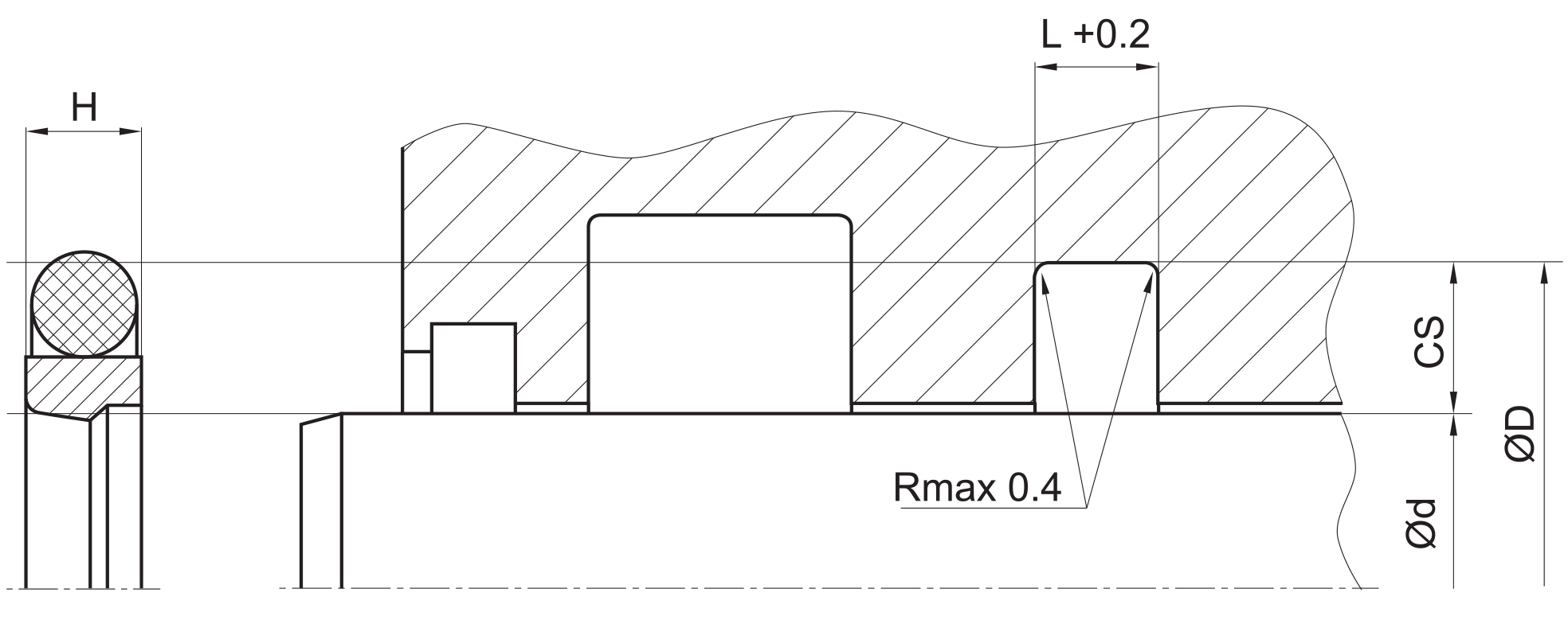
recommended housing for S09-P
| L | (ØD – Ød)/2 mm | |
| ISO | standard | |
| 2.2 | 2.45 | 2.5 |
| 3.2 | 3.65 | 3.75 |
| 4.2 | 5.35 | 5.5 |
| 6.3 | 7.55 | 7.75 |
| 8.1 | 10.25 | 10.5 |
| 8.1 | 12 | 12.25 |
mode of installation
for inside diameters of 25 mm or more, and dependant on the radial cross section (cs), seal can be snapped into the housing.
| Ød | type of installation |
| ≤ 6•cs | open mounting space required |
| > 6•cs …..≤ 10•cs | snap mounting with tool |
| > 10•cs | snap mounting by hand |
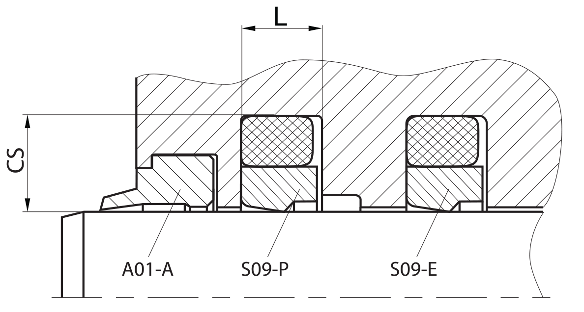
recommended mounting space:
two types of mounting space are recommended depending on application:
| primary seal | secondary seal | |
| version 1 | RS 09-B | RS 09-C |
| version 2 | RS 09-C | – |
the choice of the sealing system does not depend on the guide elements.
recommended guide tolerance D1:
in most cases the guiding elements are integrated in the piston seal system on both sides. if not use below recommendations for D1 (=inside diameter of the guiding elements):
| d f8 [mm] | p ≤ 100 [bar] | 100 < p ≤ 200 [bar] | p > 200 [bar] |
| ≤ 100 | H10 | H8 | H8 |
| > 100 ≤ 200 | H10 | H8 | H7 |
| >200 | >20 | H8 | H7 |
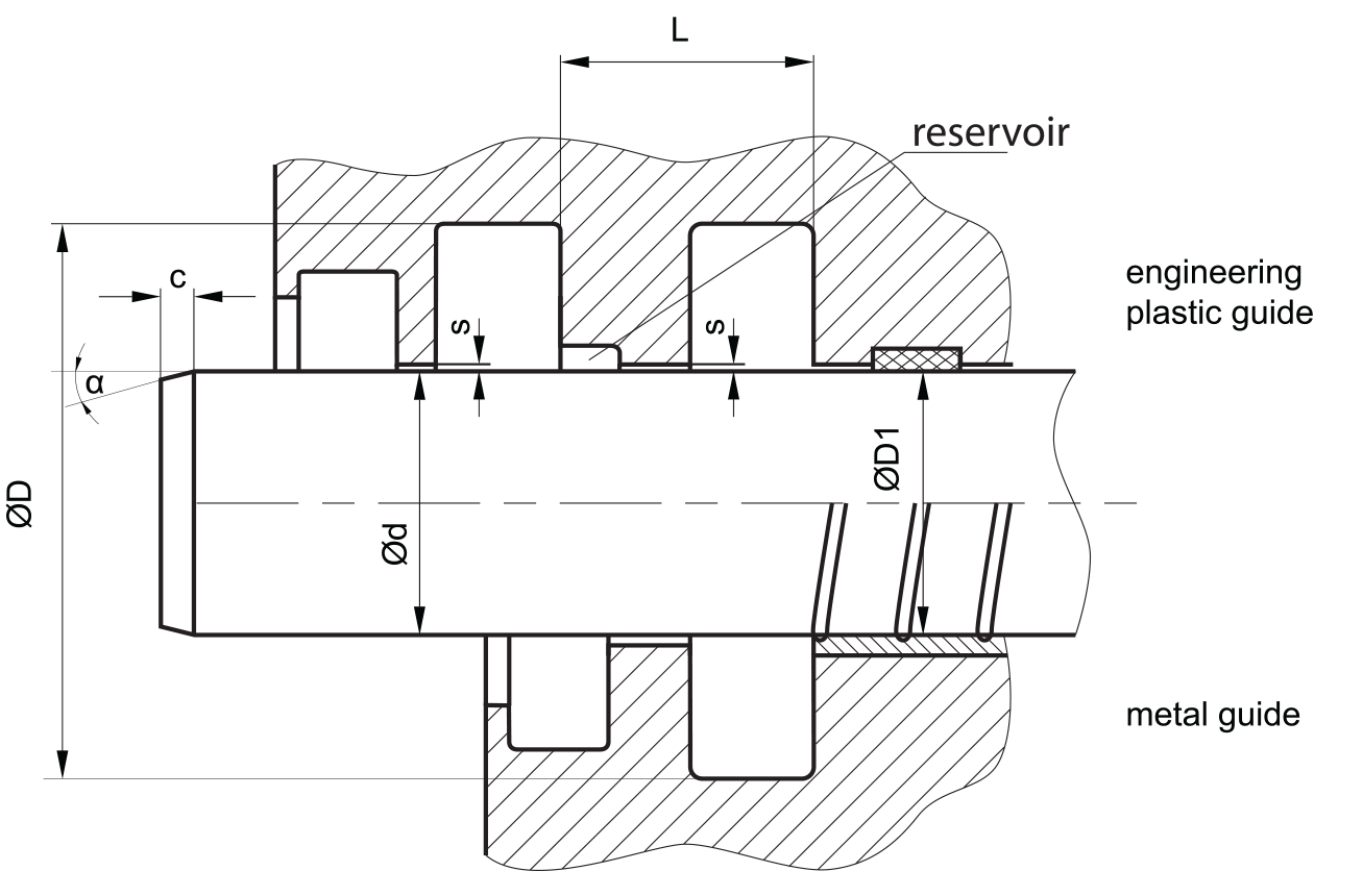
insertion chamfer:
in order to avoid damage to the rod seal during installation, the piston rod is to be chamfered and rounded as shown in the “recommended mounting space” drawing. the size of chamfer depends on the seal type and profile width.
| cs (mm) | c (mm) | |
| α = 15⁰ … 20⁰ | α = 20⁰ … 30⁰ | |
| 2.45 | 2.5 | 1.5 |
| 3.5 | 3.5 | 2 |
| 5.35 | 4.5 | 3 |
| 7.55 | 5 | 3.5 |
| 10.25 | 6 | 5 |
| 12 | 8 | 6 |
| 13.65 | 10 | 7 |
seal & housing recommendations
please note that we are able to produce those profiles to your specific need or any non standard housing. for detail measurements, please see Jet seal pars catalog…
the ratio between nominal width and seal height should be in accordance to ISO 7425 part 2. we recommend the following values:
| Ød [mm] | cs = (ØD – Ød)/2 [mm] | L [mm] |
| 5 ~ 7,9 | 2,45 | 2,2 |
| 8 ~ 18,9 | 3,65 | 3,2 |
| 19 ~ 37,9 | 5,35 | 4,2 |
| 38 ~ 199,9 | 7,55 | 6,3 |
| 200 ~ 255,9 | 10,25 | 8,1 |
| 256 ~ 649,9 | 12 | 8,1 |
fitted:
don’t hesitate to contact our technical department for further information or for special requirements (temperature, speed etc.), so that suitable materi- als and/or designs can be recommended.