

Description
the rod seal RS09-D is an rubber energised plastic faced seal. the seal is designed to expand and improve the service parameters of O-Rings and is installed in existing O-Ring grooves.
RS 09-D combines the flexibility and response of O-Rings with the wear and friction characteristics of the PTFE+…. materials in dynamic applications.
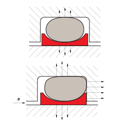
the figures below shows the cross section of the RS09-D.
the double acting performance of the seal follows from the symmetrical cross section which allow the seal to respond to pressure in both directions.
initial contact pressure is provided by radial compression of the O-Ring. when the system pressure is increased the O-Ring transforms this into additional contact pres- sure, the contact pressure of the seal is thereby automatically adjusted so sealing is ensured under all service conditions.
application

category of profile
machined or molded/standard/trade product.
double acting
the S09-SB seal is designed for use as a rod seal.
area of application: hydraulics
the RS09 D is preferably used as a double acting seal for hydraulic and pneumatic equipment in sectors such as:
- machine tools
- handling devices
- manipulators
- valves
- chemical process equipments.
it is particular recommended for light duty and small diameter applications.
notches
RS09-D is as standard supplied without radial notches, as the thin radial section of the seal gives good response to pressure variations. for diameters from 8 mm notches on both sides are optional. these ensure direct pressurizing of the seal under all operating conditions.

advantages
- compact groove dimensions and simple installation.
- low friction without stick-slip.
- resistance against wear and extrusion.
- rod seals available for all diameters from 2 to 999.9 mm.
- standard cross sections cover AS 568A and important metric O-Rings, other cross sections available on request.
- fits also groove dimensions per MIL-G-5514F.
operating parameters & material for standard application:
| material | temperature˚C | max-surface speed | max-pressure | |
| sealing element | energizer | |||
| PTFE 40% bronze | NBR 70 SH-A | -30˚C … + 100 | 15 m/s | 350 bar (350 MPa) |
| TNBR 70 SH-A | -45˚C … + 80 | 15 m/s | 350 bar (350 MPa) | |
| FPM 70 SH-A | -10˚C … + 200 | 15 m/s | 350 bar (350 MPa) | |
for hydraulic components with reciprocating movement in mineral oils containing zinc or medium with good lubricating performance and hard mating surface.
standard material for hydraulics, high compressive strength, good sliding and wear properties, good extrusion resistance, BAM tested. mating surface material: steel tubes, steel hardened cast iron.
colour: greyish to dark brown.
operating parameters & material for special application:
| material | temperature˚C | max-surface speed | max-pressure | |
| sealing element | energizer | |||
| PTFE carbon | NBR 70 SH-A | -30˚C … + 100 | 15 m/s | 250 bar (25 MPa) |
| TNBR 70 SH-A | -45˚C … + 80 | 15 m/s | 250 bar (25 MPa) | |
| FKM 70 SH-A | -10˚C … + 200 | 15 m/s | 250 bar (25 MPa) | |
| EPDM 70 SH-A | -45˚C … + 145 | 15 m/s | 250 bar (25 MPa) | |
short stroke movements, poor lubricating fluids and soft mating surfaces. for all lubricating and non-lubricating hydraulic fluids, soft mating surfaces.
mating surface material: steel, steel hardened cast iron, stainless steel, aluminium, bronze. colour: black
important note:
the above data are maximum values and cannot be used at the same time. e.g. the maximum operating speed depends on material type, pressure, temperature and gap value. temperature range also dependent on medium.
1 pressure ratings are dependent on the size of the extrusion gap.
2 attention: not suitable for mineral oils!
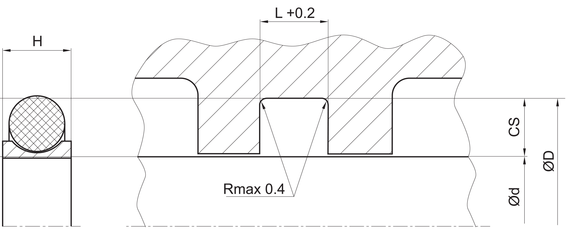
installation dimensions
| rod diameter – d (f8/h9) | D (H9) | L + 0,2 | r | max. permissible gap dimension – s 1 | O-Ring cross section | ||||
| standard application | light application | 2 MPa | 10 MPa | 20 MPa | 35 MPa | ||||
| 4 ~9,9 | 2 ~129,9 | d + 2,9 | 2,4 | 0.4 | 0.10 | 0.10 | 0.08 | 0.05 | 1.78 |
| 10 ~19,9 | 5 ~249,9 | d + 4,5 | 3.6 | 0.4 | 0.15 | 0.15 | 0.10 | 0.07 | 2.62 |
| 20 ~39,9 | 5 ~449,9 | d + 6,2 | 4.8 | 0.6 | 0.25 | 0.20 | 0.15 | 0.08 | 3.53 |
| 40 ~119,9 | 12 ~649,9 | d + 9,4 | 7.1 | 0.8 | 0.35 | 0.25 | 0.20 | 0.10 | 5.33 |
| 120 ~649,9 | 60 ~ 999,9 | d + 12,2 | 9.5 | 0.8 | 0.50 | 0.30 | 0.25 | 0.15 | 7.00 |
| 650 ~999,9 | 110 ~999,9 | d + 15,0 | 10.0 | 1.0 | 0.60 | 0.40 | 0.30 | 0.20 | 8.40 |
important note:
the above data are maximum values and cannot be used at the same time. e.g. the maximum operating speed depends on material type, pressure, temperature and gap value. temperature range also dependent on medium.
1 at pressures > 40 MPa use diameter tolerance H8/f8 (bore/piston) in area of the seal. the radial clearance is valid for material PTFE + Bronze at
+60°C.
surface quality
| surface roughness |
material |
Rtmax [µm] |
Rz DIN [µm] |
Ra [µm] |
| mating surface | PTFE + …… | 0.63 – 2.50 | 0.40 – 1.60 | 0.05 – 0.20 |
| PU & Rubber | 1.00 – 4.00 | 0.63 – 2.50 | 0.10 – 0.40 | |
| groove surface | < 16 | < 10.0 | < 1.6 | |
tolerance recommendation
| seal housing | tolerances |
| Ød | f8/h9 |
| ØD | H9 |
seal & housing recommendations
please note that we are able to produce those profiles to your specific need or any non standard housing. for detail measurements, please see Jet seal pars catalog…
don’t hesitate to contact our technical department for further information or for special requirements (temperature, speed etc.), so that suitable materi- als and/or designs can be recommended.