

description
chevron sealing set, machined surface design. for heavy industry hydraulics.
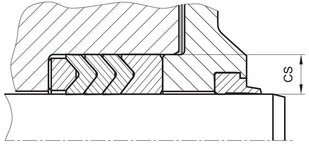
- symmetric single-acting rod sealing set consisting of several chevrons, combined with pressure and support ring to form a set.
- various materials are available for different purposes.
- good sealing in all pressure ranges,particularly in the low pressure range.
- for pressures up to 500 bar as a seal between pressurized space and atmosphere.
- excellent static and dynamic sealing.
- suitable for short and long travel.
- very sturdy and wear-resistant.
- insensitive to thermal damage caused by air in the oil.
- open, preferably adjustable,mounting space required (see mode of installation).
- the sealing packing can be used both as a rod seal and single-acting piston seal.
- by combining various materials,the packing can be adjusted to the operatingconditions.
- by varying the number of packings,friction as well as leakage behavior can beinfluenced.
- for easier installation, seals can be split (see mode of installation).
- mainly used for repair purposes. use more modern systems for new designs.
application

not bolded symbols; please consult our technical for application limitations
category of profile
machined only.
single acting
the RS1012 seal is designed for use as a rod seal.
area of application: hydraulics
- reciprocating rods on hydraulic cylinders; small swiveling motion also permissible.
- especially for heavy hydraulic applications or heavy-dutyoperating conditions.
- for repairs of heavy machinery and for normal wear,when re-tightening is possible.
note
- expensive and complex design.
- high degree of friction and thus little mechanical efficiency.
- for small numbers.for large amounts, the RS1012 profile is preferred.
- too many chevrons or too high clamping torque at installation can load to increased friction and wear (for standing applications usemaximum 3-4 chevrons).
- if a split version is used,the packings must be made slightly larger (approx. 1% in the diameter). the packing as well as the pressureand male ring are cut straight. at least 3 packings should be provided, preferably 5.
function
RS1012 profiles are single-acting rod chevron sets designed to seal pressurized space against the atmosphere; mainly for reciprocating movements. the design is based on application in standard hydraulic systems with conventional hydraulic oils. the operating parameters are as defined in the sealing data sheet and material data. requirements deviating from these parameters can be met to a certain degree by changing the geometry in the software program.
operating parameters & material (max. pressure=500 bar (50 MPa))
| material | temperature °C | max. surface speed | hydrolysis | dry running | wear resistance | ||
| RS10 | RS11 | RS12 | |||||
| POM/PA | PU | POM/PA | -30 … +100 | 0,5 m/s | – | + | + |
| POM/PA | HPU | POM/PA | -20 … +100 | 0,5 m/s | + | + | + |
| POM/PA | LTPU | POM/PA | -40 … +100 | 0,5 m/s | – | + | + |
| POM/PA | SPU | POM/PA | -20… +100 | 0,7 m/s | + | + | + |
| POM/PA | CPU | POM/PA | -30 … +100 | 0,5 m/s | + | + | + |
| PTFE glass | NBR | PTFE glass | -30 … +100 | 0,5 m/s | – | – | O |
| PTFE glass | FKM | PTFE glass | -20 … +200 | 0,5 m/s | – | – | O |
| PTFE glass | EPDM | PTFE glass | -50 … +150 | 0,5 m/s | ++ | – | O |
| PTFE glass | HNBR | PTFE glass | -25 … +150 | 0,5 m/s | + | O | + |
the stated operation conditions represent general indications. it is recommended not to use all maximum values simultaneously. surface speed limits apply only to the presence of adequate lubrication film.
1 pressure ratings are dependent on the size of the extrusion gap.
2 POM up to ø260 mm, PA above ø260 mm.
++ … particularly suitable o … conditional suitable
+ … suitable – … not suitable
for detailed information regarding chemical resistance please refer to our „list of resistance“. for increased chemical and thermal resistance rubber
materials are to be preferred, polyurethane materials increase wear resistance. for higher gliding speeds another sealing system should be used (e.g. PTFE materials).
gap dimension
when using a pressure ring, the extrusion gap is already integrated in the seal. the gap between piston rod and housing should not exceed cs·0.05.
manufacturing notes
the following nominal widths are preferred. the theoretical packing height SH11 should be designed in accordance with the recommended values;
| CS | SH11 |
| (4) | 2.2 |
| 5 | 2.5 |
| (6) | 3.0 |
| 7.5 | 3.5 |
| 10 | 5.0 |
| 12.5 | 6.0 |
| 15 | 7.5 |
| 20 | 10 |
| (25) | 12.5 |
| (30) | 15 |
in order to be able to maintain the required height irrespective of the accumulated packing height ‘h’, the pressure ring is individually adjusted during the production of the V-packing set. to do so, a control dimension is provided by the machine software with a view to assisting this process.
surface quality
| surface roughness |
Rtmax (μm) |
Ra (μm) |
| sliding surface | ≤2,5 | ≤0,1-0,5 |
| bottom of groove | ≤6,3 | ≤1,6 |
| groove face | ≤15 | ≤3 |
tolerance recommendation
| seal housing | tolerances |
| Ød | f8 |
| ØD | H10 |
mode of installation
insert the male ring first, then the packing and finally the pressure ring (well greased) into the installation space. insert the metal insert without load, complete mounting of the system, tighten metal inserts slightly, let run in (10 to 20 idle strokes); re-tighten depending on leakage. in the case of wear, re-tightening is also possible.
if split seals are used, the packing should be fitted by separating the split ends axially (twisting). joints should be staggered by 90 to 120 degrees relative to each other. split ends should be inserted into the groove first and then the remainder of the seal is pressed in.
recommended mounting space:
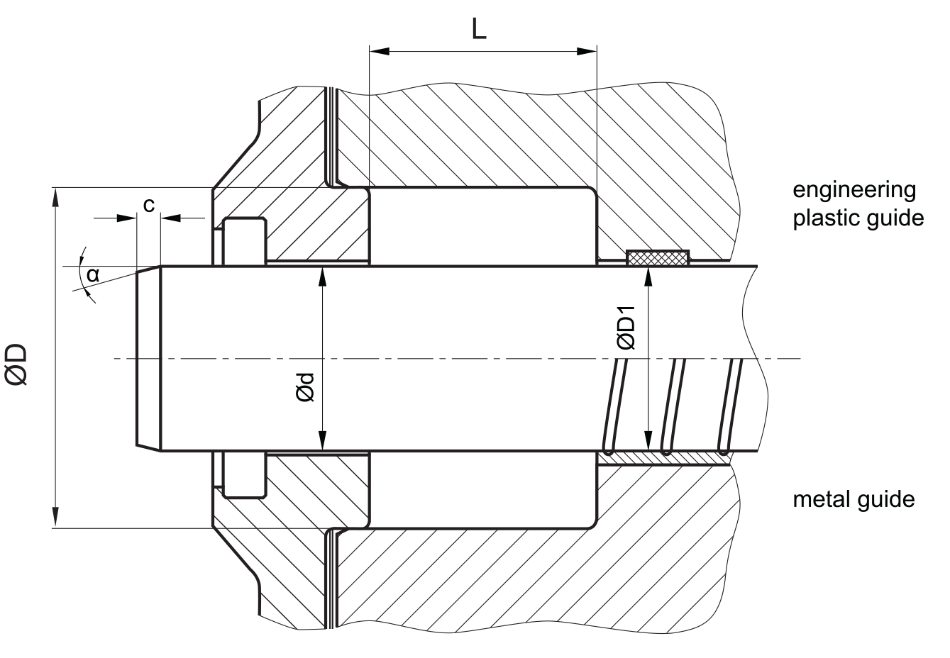
the adjustment range of the mounting space height (L) should correspond to approx. 10% of the theoretical mounting length. a guideline for the height of the spacer should be approx. 30% of the cross section.
recommended guide tolerance D1:
| d f8 [mm] |
p ≤ 100 [bar] |
100 < p ≤ 200 [bar] |
p > 200 [bar] |
| ≤ 100 | H10 | H8 | H8 |
| > 100 ≤ 200 | H10 | H8 | H7 |
| >200 | H9 | H8 | H7 |
insertion chamfer:
in order to avoid damage to the rod seal during installation, the piston rod is to be chamfered and rounded as shown in the “recommended mounting space” drawing. the size of chamfer depends on the seal type and profile width.
| cs (mm) | c (mm) | |
| α = 15⁰ … 20⁰ | α = 20⁰ … 30⁰ | |
| 4 | 3.5 | 2 |
| 5 | 4 | 2.5 |
| 6 | 4.5 | 3 |
| 7.5 | 5 | 4 |
| 10 | 6 | 5 |
| 12.5 | 8.5 | 6.5 |
| 15 | 10 | 7.5 |
| 20 | 13 | 10 |
seal & housing recommendations
please note that we are able to produce those profiles to your specific need or any non standard housing. for detail measurements, please see Jet seal pars catalog…

the ratio between nominal width and seal height should be in accordance with following recommendations (see also manufacturing notes)
| Ød [mm] | ØD [mm] | L [mm] | cs = (ØD – Ød)/2 [mm] |
| 10 – 39,9 | ød + 10 | 16 | 5 |
| 40 – 74,9 | ød + 15 | 25 | 7.5 |
| 75 – 149,9 | ød + 20 | 32 | 10 |
| 150 – 199,9 | ød + 25 | 40 | 12.5 |
| 200 – 300 | ød + 30 | 50 | 15 |
| > 300 | ød + 40 | 63 | 20 |
fitted:
don’t hesitate to contact our technical department for further information or for special requirements (temperature, speed etc.), so that suitable materi- als and/or designs can be recommended.