

description
as profile RS17-A1, but more adaptation possibilities for diverse temperatures and media by selection of suitable seal material.
- asymmetric single-acting rod lip seal, with the dynamic sealing lip being shorter than the static one.
- interference fit on the outside diameter.
- various materials are available for different purposes.
- snaps into simple grooves (see notes on installation).
- best sealing effect across a wide temperature range.
- for pressures up to 160 bar as a seal between pressurised space and atmosphere.
- good sealing in the low pressure range.
- excellent static and dynamic sealing.
- the secondary lip reduces the residual oil film.
application

not bolded symbols; please consult our technical for application limitations
category of profile
machined only.
single acting
the RS17-A1seal is designed for use as a rod seal.
area of application: hydraulics
- reciprocating rods on hydraulic cylinders,push rods, fittings.
- rod seals for applications with small extrusion gap and without specific impact load.
- commonly used as sealing element in telescopic cylinders (for large deflections increased preload may be necessary).
- can also be used as a pivot seal at low loads (e.g.end seal in rotary pivots).
note
- this seal has the correct functioning dimension only when mounted. when slipping the seal over the piston rod, it may appear too big.
- the ratio between nominal width and sealing height cs/H should not drop below a value of 1/1.25 (essentially according to ISO 5597 housings for piston and rod seals).
- on long strokes drag pressure may be built up between both lips,which can lead to disfunction.
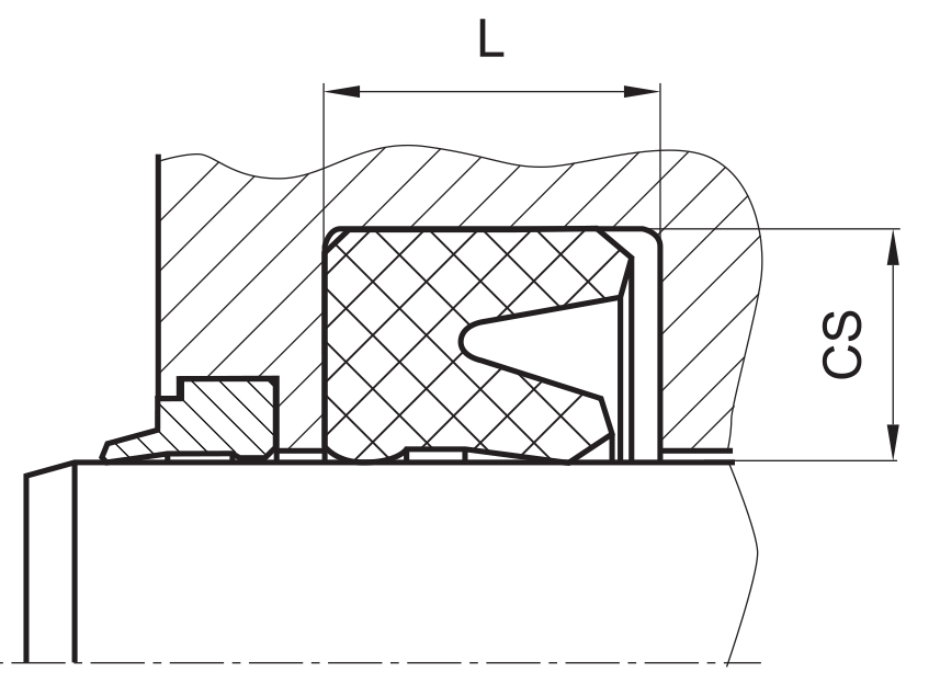
function
RS17-A1profiles are lip seals designed to seal pressurised space against the atmosphere; mainly for reciprocating movements. the secondary lip on the back ensures a increased stability in the housing. the design is based on application in standard hydraulic systems with con- ventional hydraulic oils. the operating parameters are as defined in the sealing data sheet and material data. requirements deviating from these parameters can be met to a certain degree by changing the geometry in the software program.
operating parameters & material
| material | temperature | max. surface speed | max. pressure 1 | hydrolysis | dry running | wear resistance |
| NBR | -30 °C … +100 °C | 0,5 m/s | 160 bar (16 MPa) | – | – | O |
| FKM | -20 °C … +200 °C | 0,5 m/s | 160 bar (16 MPa) | – | – | O |
| EPDM | -50 °C … +150 °C | 0,5 m/s | 160 bar (16 MPa) | ++ | – | O |
| HNBR | -25 °C … +150 °C | 0,5 m/s | 160 bar (16 MPa) | + | O | + |
| MVQ | -60 °C … +200 °C | – | – | ++ | – | – |
the stated operation conditions represent general indications. it is recommended not to use all maximum values simultaneously. surface speed limits apply only to the presence of adequate lubrication film.
1 pressure ratings are dependent on the size of the extrusion gap.
2 attention: not suitable for mineral oils!
++ … particularly suitable o … conditional suitable
+ … suitable – … not suitable
for detailed information regarding chemical resistance please refer to our „list of resistance“. for increased wear resistance and higher pressure range
polyurethane materials are to be preferred, attention should be paid to restrictions in chemical and thermal resistance. for higher gliding speeds another sealing system should be used (e.g. PTFE materials).
gap dimension
| operating pressure | cs = (ØD – Ød)/2 mm | |||||
| 4 | 5 | 7.5 | 10 | 12.5 | 15 | |
| safe extrusion gap (mm) | ||||||
| 50 bar (5 MPa) | 0.20 | 0.22 | 0.28 | 0.30 | 0.35 | 0.38 |
| 100 bar (10 MPa) | 0.18 | 0.19 | 0.25 | 0.27 | 0.31 | 0.37 |
| 160 bar (16 MPa) | 0.15 | 0.17 | 0.20 | 0.25 | 0.28 | 0.32 |
important note:
the above data are maximum value and can’t be used at the same time. e.g. the maximum operating speed depend on material type, pressure, tem- perature and gap value. temperature range also dependent on medium.
the diagram applies to an operating temperature of 70 °C.
surface quality
| surface roughness |
Rtmax (μm) |
Ra (μm) |
| sliding surface | ≤2,5 | ≤0,1-0,5 |
| bottom of groove | ≤6,3 | ≤1,6 |
| groove face | ≤15 | ≤3 |
tolerance recommendation
| seal housing | tolerances |
| Ød | f8 |
| ØD | H10 |
mode of installation
for inside diameters of 25mm or more, and dependant on radial cross section (cs), seals may be snapped into closed housings.
| Ød | type of installation |
| ≤ 6•cs | open mounting space required |
| > 6•cs …..≤ 10•cs | snap mounting with tool |
| > 10•cs | snap mounting by hand |
recommended mounting space:
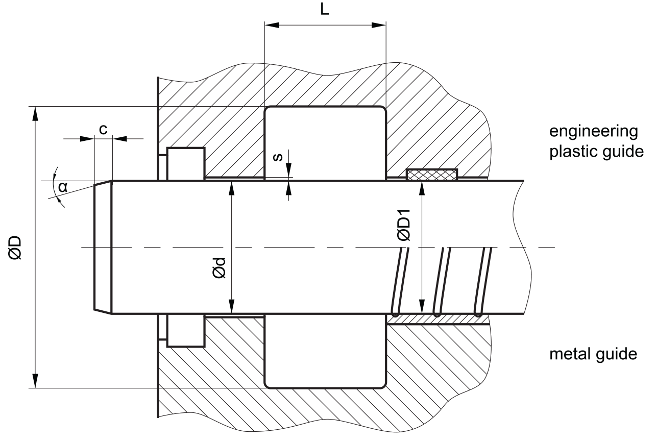
recommended guide tolerance D1:
| d f8 [mm] |
p ≤ 100 [bar] |
100 < p ≤ 200 [bar] |
p > 200 [bar] |
| ≤ 100 | H10 | H8 | H8 |
| > 100 ≤ 200 | H10 | H8 | H7 |
| >200 | H9 | H8 | H7 |
insertion chamfer:
in order to avoid damage to the rod seal during installation, the piston rod is to be chamfered and rounded as shown in the “recommended mounting space” drawing. the size of chamfer depends on the seal type and profile width.
| cs (mm) | c (mm) | |
| α = 15⁰ … 20⁰ | α = 20⁰ … 30⁰ | |
| 4 | 3.5 | 2 |
| 5 | 4 | 2.5 |
| 6 | 4.5 | 3 |
| 7.5 | 5 | 4 |
| 10 | 6 | 5 |
| 12.5 | 8.5 | 6.5 |
| 15 | 10 | 7.5 |
| 20 | 13 | 10 |
seal & housing recommendations
please note that we are able to produce those profiles to your specific need or any non standard housing. for detail measurements, please see Jet seal pars catalog…
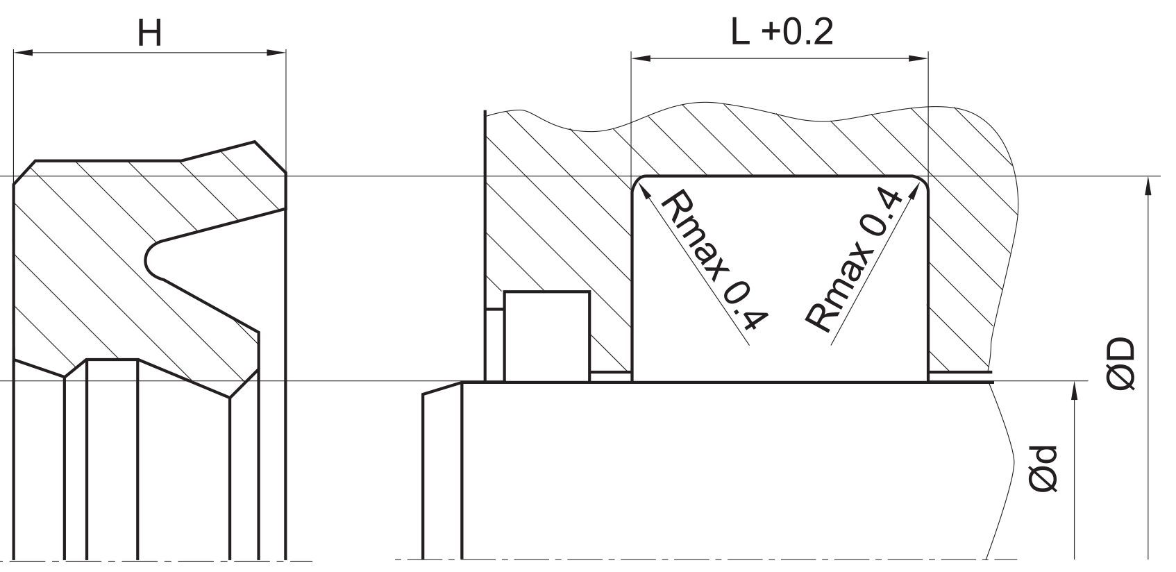
the ratio between nominal width and seal height cs/H should not drop below 1/1,25. therefore we recommend the following housing heights.
| cs = (ØD – Ød)/2 [mm] | L [mm] |
| 8 | 4 |
| 9 | 5 |
| 11 | 6 |
| 14 | 7.5 |
| 17 | 10 |
| 20 | 12.5 |
| 25 | 15 |
| 32 | 20 |
fitted:
don’t hesitate to contact our technical department for further information or for special requirements (temperature, speed etc.), so that suitable materi- als and/or designs can be recommended.