

description
fingerspring activated PTFE seal with integrated clamping flange on the back of seal for clamping fixation, acting as anti-twist device. excellent chemical and thermal resistance. suitable for relatively high pressure and high speed, however, allowable pressure and speed depend on each other, it is not recommended to use all maximum values simultaneously.
application

category of profile
machined or molded/standard/trade product.
single acting PTFE rotary seal
area of application:
diverse applications in all branches of general mechanical and apparatus engineering, hydraulics and pneumatics, chemical and process- ing technology. rotating, swivelling, reciprocating and combined (lifting and rotating) movements.
advantages
- rotary, reciprocating and static service
- good scraping effect
- stick-slip-free operating for precise control
- high abrasion resistance and dimensional stability
- can handle rapid changes in temperature
- no contamination in contact with foodstuffs, pharmaceutical and medicinal fluids
- sterilisable
- unlimited shelf life.
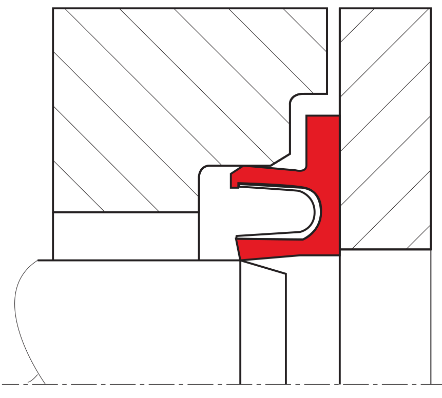
function
the RS 19-A is a single function, inside sealing U-ring with a clamp fitting which prevents simultaneous turning. the sealing lips are of varying design which optimizes the sealing power and reduces friction with the result of the seal having an exceptionally good service life. the metal spring permanently activates the sealing lips which guarantees zero leackage even in an unpressurised state.
media
all types of hydraulic oils, hot air, steam, most chemicals.
| Material | temperature | max. surface speed | max. pressure 1 | |
| sealing element | spring | |||
| PTFE glass | 14.310 | -200 °C … +260 °C | 15 m/s | 300 bar (30 MPa) |
| PTFE glass | 14.310 | -200 °C … +260 °C | 15 m/s | 300 bar (30 MPa) |
| PTFE bronze | 14.310 | -200 °C … +260 °C | 15 m/s | 300 bar (30 MPa) |
| all material possible | 14.310 | choice is dependent upon application (preload, …) | ||
the stated operation conditions represent general indications. it is recommended not to use all maximum values simultaneously. surface speed limits apply only to the presence of adequate lubrication film.
1 pressure ratings are dependent on the size of the extrusion gap.
| (D1-d)/2 | spring |
| 3 … 4.6 mm | 6,35 x 0,15 |
| >4.6 … 6 mm | 9,8 x 0,18 |
| >6 … 8 mm | 14,1 x 0,22 |
surface quality
| surface roughness |
Rtmax (μm) |
Ra (μm) |
| rotating | ≤ 1 -2,5 | ≤ 0,1-0,2 |
| linear | ≤ 2,5-4 | ≤ 0,2-0,4 |
tolerance recommendation
| seal housing | tolerances |
| Ød | f8/h9 |
| ØD | H10 |
| ØD1 | H9 |
| ØL1 ≤ 1,35 | -0,1 |
| ØL > 1,35 … ≤ 1,8 | -0,15 |
| ØL > 1,8 | -0,2 |
frictional power
guide values for the frictional power can be determined from the graphs in figure below. they are shown as a function of the sliding speed and operating pressure for a shaft diameter of 50 mm with an oil temperature of 60 °C. at higher temperatures, these application limits must be reduced.
guide values for other shaft diameters can be calculated using the formula:
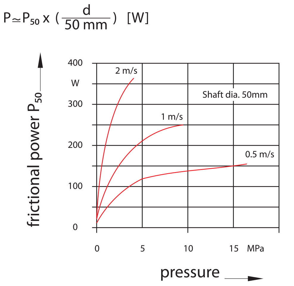
the guide values apply for constant operating conditions. changes in operating conditions such as pressure fluctuations or alternating directions of shaft rotation can result in considerably higher friction values.
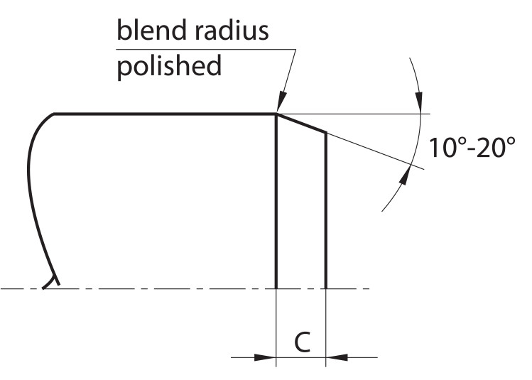
lead-in chamfers
in order to avoid damage during installation, lead-in chamfers and rounded edges must be provided on the housing and on the rod (figure below). if this is not possible for design reasons, a separate installation tool is recommended.
the minimum length of the lead-in chamfer depends on the profile size of the seal and can be seen from the following tables. if concentricity between the parts is not ensured during installation the lead-in chamfers must be increased correspondingly.
for the surface quality of the lead-in chamfer, the same recommendations apply as given for the sealing surfaces in housing recommendation.
installation
installation instructions
the following points should be observed before installation of the seals:
- check whether housing or rod has a lead-in chamfer; if not, use an installation sleeve
- deburr and chamfer or round sharp edges, cover the tips of any screw threads
- remove machining residues such as chips, dirt and other foreign particles and carefully clean all parts
- if the seals are installed with grease or oil, attention must be paid to the compatibility of the seal materials with these lubricants. use only grease without solid additives (e.g. molybdenum disulphide or zinc sulphide)
- do not use installation tools with sharp edges
installation of R19-F
the R19-F is installed in split grooves.
installation should be performed in the following steps in order to ensure a concentric and strain-free fit:
-place the seal ring in into the open groove
-fit the cover loosely onto the housing
-insert the shaft
-tighten the cover
seal & housing recommendations
please note that we are able to produce those profiles to your specific need or any non standard housing. for detail measurements, please see Jet seal pars catalog…
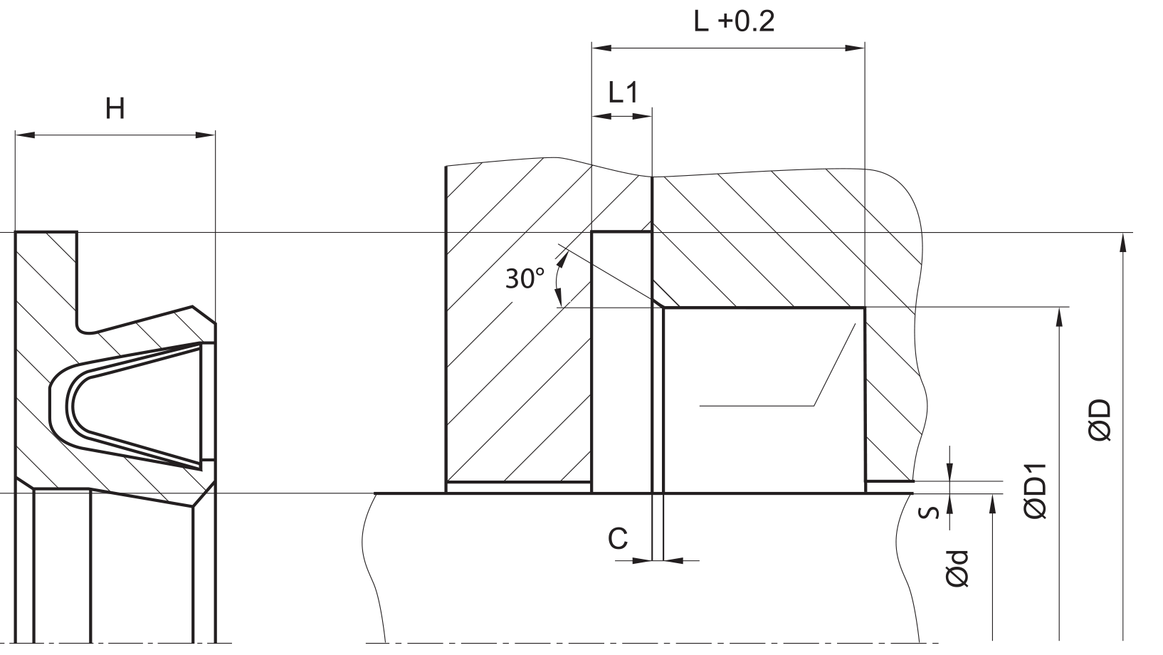
| Material | ØD (mm) | ØD1 (mm) | L (mm) | L1 (mm) | c (lead in chamfer) (mm) | R (mm) | s max. safe extrusion gap [mm] | ||||
| sealing element | spring | 2MPa | 10MPa | 20MPa | c (mm) | ||||||
| 5,0 – 19,9 | 5,0 – 200,0 | Ød + 9,0 | Ød + 5,0 | 3.6 | 0,85 +0 -0,1 | 0.3 | 0.8 | 0.25 | 0.15 | 0.1 | 4.5 |
| 20,0 – 39,9 | 10,0 – 400,0 | Ød + 12,5 | Ød + 7,0 | 4.8 | 1,35 +0 -0,15 | 0.4 | 1.1 | 0.35 | 0.2 | 0.15 | 5 |
| 40,0 – 399,9 | 20,0 – 700,0 | Ød + 17,5 | Ød + 10,5 | 7.1 | 1,80 +0 -0,20 | 0.5 | 1.4 | 0.5 | 0.25 | 0.2 | 8 |
| 400,0 – 999,9 | 35,0 – 999,9 | Ød + 22,0 | Ød + 14,0 | 9.5 | 2,80 +0 – 0,20 | 0.5 | 1.6 | 0.6 | 0.3 | 0.25 | 12 |
don’t hesitate to contact our technical department for further information or for special requirements (temperature, speed etc.), so that suitable materi- als and/or designs can be recommended.