

description
space saving, compact rod seal, fits standard O-Ring housings. advantage compared to O-Ring: integrated active back-up rings for high pressure, design with interference fit on outside diameter maintains non-twisting in dynamic applications.
- asymmetric double-acting rod compact seal. the preload is achieved by the inter- nal stress of the seal material.
- interference fit on the outside diameter.
- various materials are available for different purposes.
- snaps into simple grooves (see notes on installation).
- good sealing effect across a wide temperature range.
- sealing effect enhanced by high recovery rate.
- for pressures up to 700 bar as a seal between pressurised space and atmosphereor between pressurised spaces.
- good sealing in the low pressure range.
- excellent static sealing.
- little inclination to“stick-slip”.
- the housing grooves are same as housing grooves for O-rings(see “range ofprofile sizes”)
- the activated back up rings reduce the risk of gap extrusion and prevent twistingin dynamic applications.
- space-saving design.
application

not bolded symbols; please consult our technical for application limitations
category of profile
machined only.
double acting
the RS 20 seal is designed for use as a rod seal.
area of application: hydraulics
- static and dynamic seals in hydraulic and pneumatic systems.
- use in systems with O-ringgrooves instead of O-rings in case of stability problems (twisting) or “pumping”.
- for valve seals in offshore and aviation applications.
note
- the design is based on standard O-ring dimensions according AS 568 A (american O-ring dimensions). in case of large deviations from standard groove dimensions the profile has to be checked .
- a design in PU materials is not recommendable because of the large deformation force
- recovery rate is lower compared to standard lip seals.
- high break-awayload after prolonged periods of standstill.
function
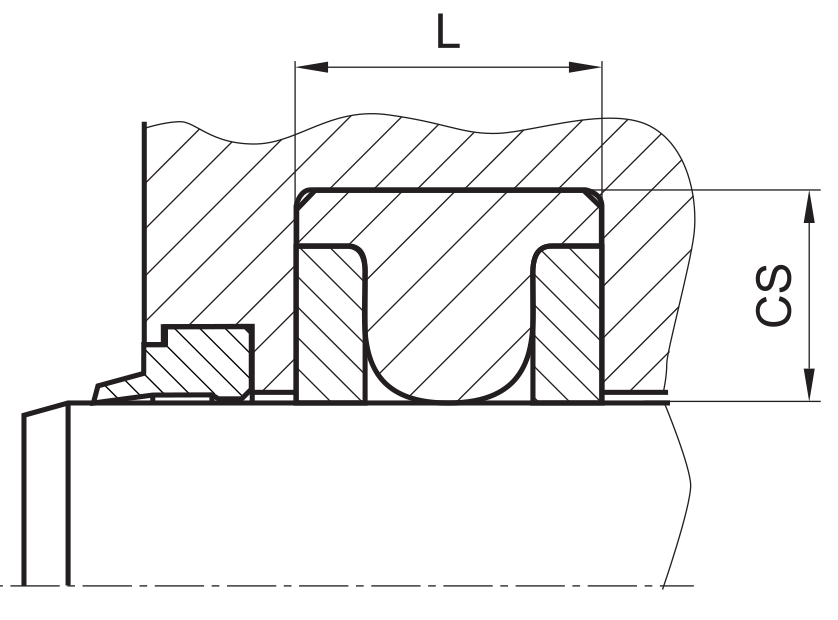
RS 20 profiles are compact seals designed to seal pressurised space against the atmosphere or between pressurised spaces mainly for re- ciprocating movements, but for slight rotations as well. the design is based on application in standard hydraulic systems with conventional hydraulic oils, the use in pneumatic systems is furthermore possible. the operating parameters are as defined in the sealing data sheet and material data. requirements deviating from these parameters can be met to a certain degree by changing the geometry in the software program.
operating parameters & material
| sealing element | back-up ring | temperature | max. surface speed | max. pressure 1 | hydrolysis | dry running | wear resistance |
| NBR | POM / PA2 | -30 °C … +100 °C | 0,5 m/s | 700 bar (70 MPa) | – | – | O |
| HNBR | POM / PA2 | -25 °C … +100 °C | 0,5 m/s | 700 bar (70 MPa) | + | O | + |
| FKM | PEEK | -20 °C … +200 °C | 0,5 m/s | 700 bar (70 MPa) | – | – | O |
| FKM | PTFE glass | -25 °C … +200 °C | 0,5 m/s | 700 bar (70 MPa) | – | – | O |
| HNBR | PEEK | -20 °C … +150 °C | 0,5 m/s | 700 bar (70 MPa) | + | O | + |
| HNBR | PTFE glass | -25 °C … +150 °C | 0,5 m/s | 700 bar (70 MPa) | + | O | + |
the stated operation conditions represent general indications. it is recommended not to use all maximum values simultaneously. surface speed limits apply only to the presence of adequate lubrication film.
1 pressure ratings are dependent on the size of the extrusion gap.
2 POM up to ø260 mm, PA above ø260 mm
++ … particularly suitable o … conditional suitable
+ … suitable – … not suitable
for detailed information regarding chemical resistance please refer to our „list of resistance“. for increased wear resistance and higher pressure range
polyurethane materials are to be preferred, attention should be paid to restrictions in chemical and thermal resistance. for higher gliding speeds another sealing system should be used (e.g. PTFE materials).
note on special materials:
as the temperature limits are determined by POM, using special materials for the back up ring can expand the temperature limits.
gap dimension
the size of the permissible gap on the side opposite the source of pressure depends mainly on the seal material and the design of the seal. if the permissible gap dimensions are exceeded, there will be extrusion wear on the side opposite the source of pressure which may make the seal unfit for usage.
the maximum value of the permissible extrusion gap is reached when the piston or the piston rod touches one side of the cylindrical tube or the guide.
due to the small height of the back up rings and the resulting sensitivity to extrusion, the gap size is limited for all ranges of diameter, pressure and cross section by the standard hole/shaft basis fit f8/H8, influences due to thermal expansion have to be considered.
surface quality
| surface roughness |
Rtmax (μm) |
Ra (μm) |
| sliding surface | ≤2,5 | ≤0,1-0,5 |
| bottom of groove | ≤6,3 | ≤1,6 |
| groove face | ≤15 | ≤3 |
tolerance recommendation
| seal housing | tolerances |
| Ød | f7 |
| t | 0.05 |
| d | R |
| ≤ 40 | max. 0,2 |
| > 40 | max. 0,4 |
mode of installation
for inside diameters of 25 mm or more, and dependant on the radial cross section (cs), the seal can be snapped into the housing.
| Ød | type of installation |
| ≤ 6•cs | open mounting space required |
| > 6•cs …..≤ 10•cs | snap mounting with tool |
| > 10•cs | snap mounting by hand |
at installation, pay attention that the radius on the backup elements fits to the corresponding radius on the sealing element (nonsymmetric backup elements).
recommended mounting space:
recommended guide tolerance D1:
| d f8 [mm] |
p ≤ 100 [bar] |
100 < p ≤ 200 [bar] |
p > 200 [bar] |
| ≤ 100 | H10 | H8 | H8 |
| > 100 ≤ 200 | H10 | H8 | H7 |
| >200 | H9 | H8 | H7 |
standard tolerance range for piston rods is f8. If a tolerance range selection is possible f7 should be preferred.
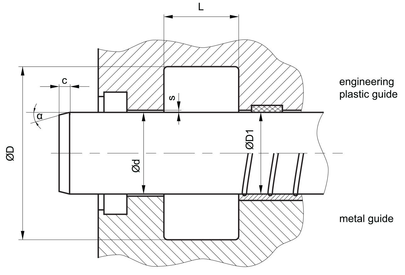
insertion chamfer:
in order to avoid damage to the rod seal during installation, the piston rod is to be chamfered and rounded as shown in the “recommended mounting space” drawing. the size of chamfer depends on the seal type and profile width.
| cs (mm) | c (mm) | |
| α = 15⁰ … 20⁰ | α = 20⁰ … 30⁰ | |
| (2) | 2 | 1 |
| (3) | 3 | 1.5 |
| 4 | 3.5 | 2 |
| 5 | 4 | 2.5 |
| 6 | 4.5 | 3 |
| 7.5 | 5 | 4 |
| 10 | 6 | 5 |
seal & housing recommendations
please note that we are able to produce those profiles to your specific need or any non standard housing. for detail measurements, please see Jet seal pars catalog…
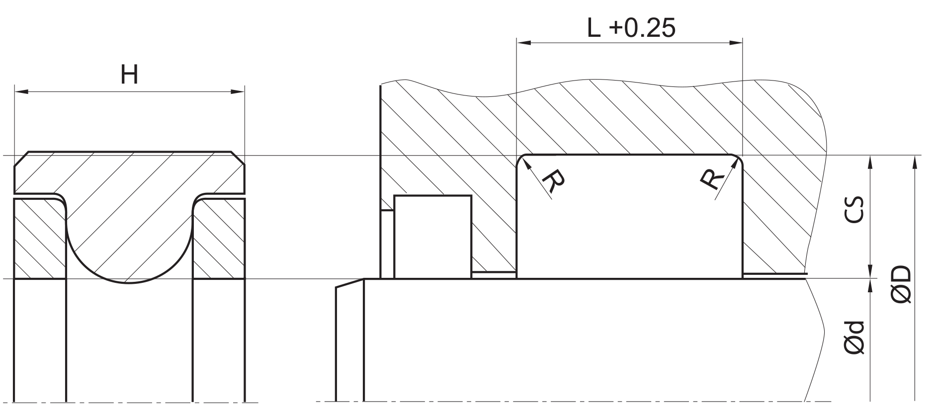
the recommendations for mounting space heights and cross sections listed below are standard values for the corresponding O-Ring without
(short), with one (medium) or with two (long) back-up rings.
| cs [mm] | corresponding O-ring [m] | mounting space height [mm] | diameter range [mm] | |||
| short | medium | long | static | dynamic | ||
| 1.35 | 1.78 | 2.5 | 3.5 | 4.5 | 11 – 99.9 | – |
| 2.18 | 2.62 | 3.5 | 5 | 6.5 | 100 – 149.9 | 11 – 19.9 |
| 3 | 3.53 | 4.4 | 5.9 | 7.4 | 150 – 249.9 | 20 – 39.9 |
| 4.53 | 5.33 | 6.7 | 8.4 | 10.1 | 250 – 399.9 | 40 – 99.9 |
| 5.94 | 6.99 | 8.8 | 10.8 | 12.8 | 400 – 599.9 | 100 – 299.9 |
| 8.5 | 10 | 12.5 | 15 | 17.5 | >600 | 300 – 600 |
fitted:
don’t hesitate to contact our technical department for further information or for special requirements (temperature, speed etc.), so that suitable materi- als and/or designs can be recommended.