
description
optimized for high pressure, equal angled chevron design suitable for high pressure range. external spring pretension necessary. mainly used in chemical, pharma and food industry.
- symmetric single-acting rod sealing set consisting of several chevrons, combined with pressure and support ring to form a set.
- the sealing function originates from the contact force applied by a spring, wear is compensated (for required spring force see “mode of installation”).
- various materials are available for different purposes.
- good sealing in the lower pressure range.
- for pressures up to 315 bar as a seal between pressurised space and atmosphere.
- good static and dynamic sealing.
- suitable for short and long travel.
- wear resistance is depending on material combina
- open mounting space required (see mode of installation).
- the sealing packing can be used both as a rod seal and single-acting piston seal.
- by varying the material, operation conditions can be adapted.
- by varying the number of packings, friction as well as leakage behavior can beinfluenced.
application

not bolded symbols; please consult our technical for application limitations
category of profile
machined or molded/standard/trade product.
single acting
the RS 2931 seal is designed for use as a rod seal.
area of application: hydraulics
- valves and pumps in corrosive environment.
- chemical, pharma, and food industry.
- high temperature applications up to 200°C.
- slight pivoting or spiral movement allowable.
note
- expensive and complex desig
- the hardness of the sliding surface should reach a minimum of 25 to 65 HRC, otherwise a damage of the sliding surface is possible(attention: acid-resistant steels do not always reach such hardness).
- if no “dead spot” is allowed in the sealing system (e.g.: food industry), the spring can be installed on the not pressurised side as well.
the spring tension then has to be increased by the value of the axial force, resulting from pressurisation (see “mode of installation”). in
this case the support ring has to be furnished with pressure relief grooves.
function
RS 2931 seal profiles are single-acting rod seal sets designed to seal pressurized space against the atmosphere; mainly for reciprocating move- ments. the design is based on application in aggressive media or with high thermal demands.
the operating parameters are as defined in the sealing data sheet and material data. requirements deviating from these parameters can be met to a certain degree by changing the geometry in the software program.
operating parameters & material
| material | temperature | max. surface speed | max. pressure 1 | hydrolysis | dry running | wear resistance | ||
| header ring S29-F | sealing element S30-F | back-up ring S31-F | ||||||
| PTFE glass | PTFE virgin | PTFE glass | -200 °C … +260 °C | 0,5 m/s | 315 bar (31.5 MPa) | ++ | ++ | O |
the stated operation conditions represent general indications. it is recommended not to use all maximum values simultaneously. surface speed limits apply only to the presence of adequate lubrication film.
1 pressure ratings are dependent on the size of the extrusion gap.
++ … particularly suitable o … conditional suitable
+ … suitable – … not suitable
for detailed information regarding chemical resistance please refer to our “list of resistance”. for decreased leackage rates elastomer materials (polyure-
thane or rubber) in other sealing systems are to be preferred.
gap dimension
the size of the permissible gap on the side opposite the pressure source depends mainly on the seal material and the design of the seal. if the permissible gap dimensions are exceeded, there will be extrusion wear on the side opposite the pressure source which may make the seal unfit for usage. the maximum value of the permissible extrusion gap is reached when the piston or the piston rod touches one side of the cylindrical tube or guide. using this seal set free of defects should include extrusion gap sizes with the same tolerance range as the guiding.
surface quality
| surface roughness |
Rtmax (μm) |
Ra (μm) |
| sliding surface | ≤2,5 | ≤0,1-0,5 |
| bottom of groove | ≤6,3 | ≤1,6 |
| groove face | ≤15 | ≤3 |
tolerance recommendation
| seal housing | tolerances |
| Ød | f8 |
| ØD | H10 |
mode of installation
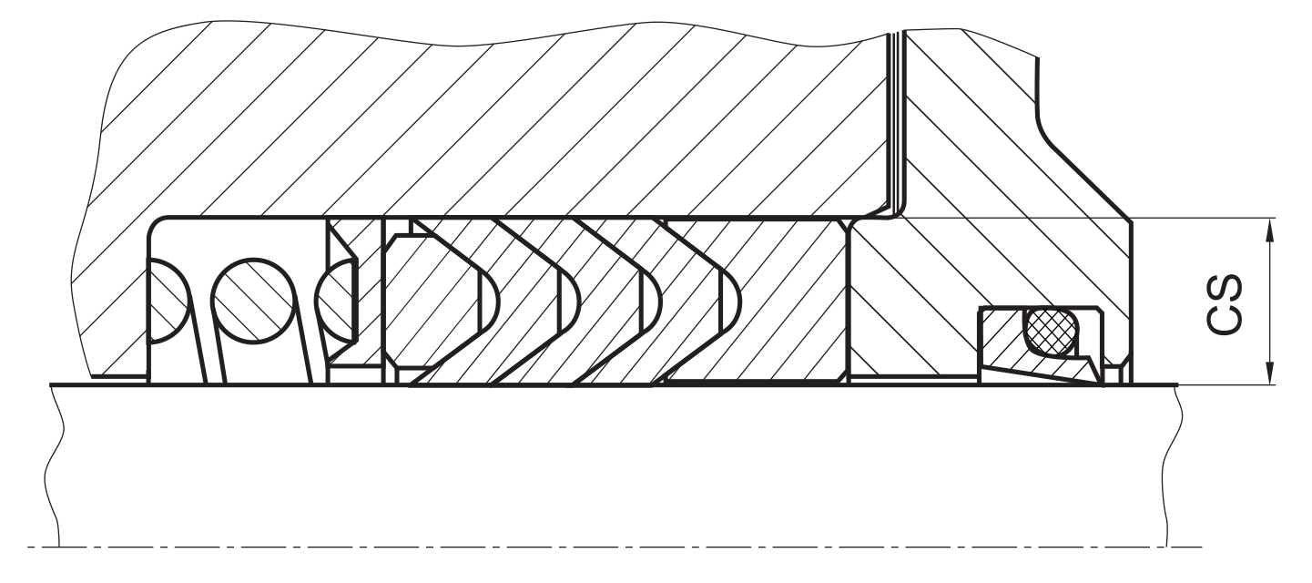
at first insert spring into housing. as far as possible, a metallic plate should be placed between spring and seal set in order to ensure a evenly dis- tributed contact pressure. pressure relief has to be provided. afterwards insert the male ring, then the packing and finally the pressure ring (well greased) into the installation space. insert the metal insert without load, complete mounting of the system, tighten metal inserts slightly, let run in (10 to 20 idle strokes). finally tighten the metal insert to nominal height.
recommended mounting space:
recommended guide tolerance D1:
| d f8 [mm] |
p ≤ 100 [bar] |
100 < p ≤ 200 [bar] |
p > 200 [bar] |
| ≤ 100 | H10 | H8 | H8 |
| > 100 ≤ 200 | H10 | H8 | H7 |
| >200 | H9 | H8 | H7 |
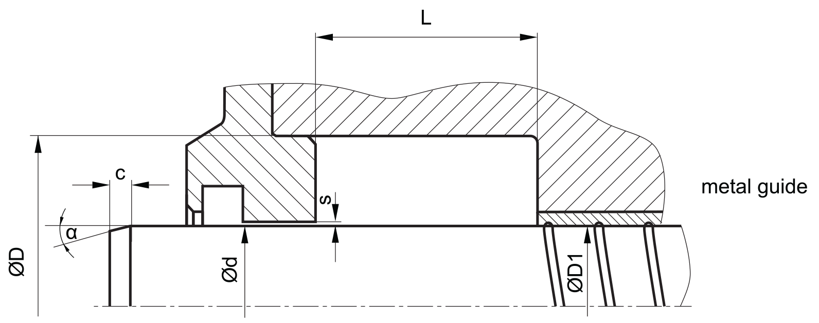
insertion chamfer:
in order to avoid damage to the rod seal during installation, the piston rod is to be chamfered and rounded as shown in the “recommended mounting space” drawing. the size of chamfer depends on the seal type and profile width.
| cs (mm) | c (mm) | |
| α = 15⁰ … 20⁰ | α = 20⁰ … 30⁰ | |
| 4 | 3.5 | 2 |
| 5 | 4 | 2.5 |
| 6 | 4.5 | 3 |
| 7.5 | 5 | 4 |
| 10 | 6 | 5 |
| 12.5 | 8.5 | 6.5 |
| 15 | 10 | 7.5 |
| 20 | 13 | 10 |
seal & housing recommendations
please note that we are able to produce those profiles to your specific need or any non standard housing. for detail measurements, please see Jet seal pars catalog…
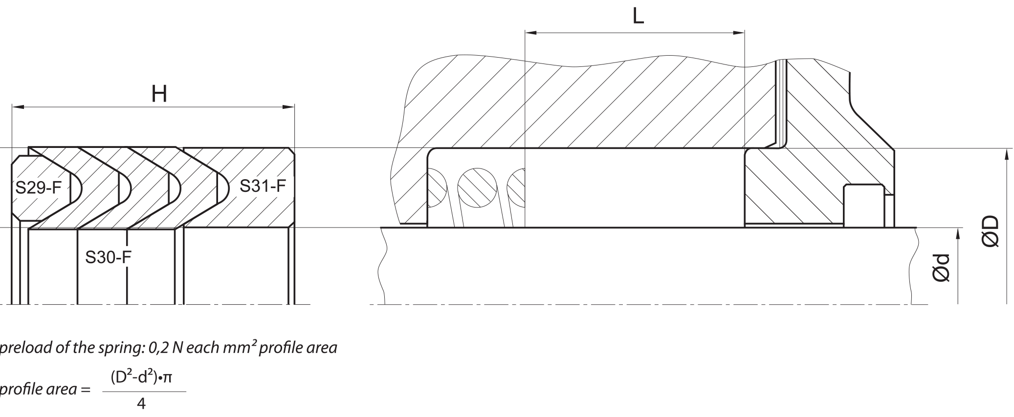
nominal width, mounting space height, cross section, diameter range and pressure should be in accordance with following recommendations:
the stated number of chevrons depends on the pressure range and is only valid for PTFE. filled PTFE series can allow lower numbers of chevron.
| Ød [mm] | ØD [mm] | L [mm] | cs = (ØD – Ød)/2 [mm] |
| 10 – 39,9 | ød + 10 | 16 | 5 |
| 40 – 74,9 | ød + 15 | 25 | 7.5 |
| 75 – 149,9 | ød + 20 | 32 | 10 |
| 150 – 199,9 | ød + 25 | 40 | 12.5 |
| 200 – 300 | ød + 30 | 50 | 15 |
| > 300 | ød + 40 | 63 | 20 |
fitted:
don’t hesitate to contact our technical department for further information or for special requirements (temperature, speed etc.), so that suitable materi- als and/or designs can be recommended.