

description
compact rod seal with almost no dead spots as required for applications in food and pharma industry, also commonly used as O-Ring replacement, because design with interference fit on outside diameter maintains non-twisting in dynamic applications.
- asymmetric double-acting rod compact seal. the preload is achieved by the inter- nal stress of the seal material.
- interference fit on the outside diameter.
- various materials are available for different purposes.
- snaps into simple grooves (see notes on installation).
- good sealing effect across a wide temperature range.
- for pressures up to 400 bar as a seal between pressurised space and atmosphereor between pressurised spaces.
- good sealing in the low pressure range.
- excellent static sealing.
- only few dead spots.
- the housing grooves are same as housing grooves for O-rings(see “range ofprofile sizes”)
- no twisting in dynamic applications.
- space-saving design.
application

not bolded symbols; please consult our technical for application limitations
category of profile
machined or molded/standard/trade product.
double acting
the RS35 seal is designed for use as a piston seal.
area of application: hydraulics
- static and dynamic seals in hydraulic systems.
- use in systems with O-ringgrooves instead of O-rings in case of stability problems (twisting) or “pumping”.
- for food and pharma applications or as a valve seal.
note
- decreasing preload in rotary applications is necessary because of high friction.
- a design in rubber materials is not recommendable because of the geometry (use S20-R).
function
S35-P profiles are compact seals designed to seal pressurised space against the atmosphere or between pressurised spaces mainly for re- ciprocating movements, but for slight rotations as well. the design is based on application in standard hydraulic systems with conventional hydraulic oils. the operating parameters are as defined in the sealing data sheet and material data. requirements deviating from these parameters can be met to a certain degree by changing the geometry in the software program.
operating parameters & material
diameter range: up to 600 mm
the stated operation conditions represent general indications. it is recommended not to use all maximum values simultaneously. surface speed limits apply only to the presence of adequate lubrication film.
1 pressure ratings are dependent on the size of the extrusion gap.
++ … particularly suitable o … conditional suitable
+ … suitable – … not suitable
for detailed information regarding chemical resistance please refer to our „list of resistance“. for increased chemical and thermal resistance rubber
materials in other sealing systems are to be preferred, attention should be paid to restrictions for pressure range and wear resistance. for higher gliding speeds another system should be used (e.g. PTFE materials).
gap dimension
| material | back-up ring | temperature | max. surface speed | max. pressure 1 | hydrolysis | dry running | wear resistance |
| PU | POM / PA | -30 °C … +110 °C | 0,4 m/s | 400 bar (40 MPa) | – | + | ++ |
| HPU | POM / PA | -20 °C … +110 °C | 0,4 m/s | 400 bar (40 MPa) | ++ | + | ++ |
| LTPU | POM / PA2 | -50 °C … +110 °C | 0,4 m/s | 400 bar (40 MPa) | – | + | ++ |
| SLPU | POM / PA | -20 °C … +110 °C | 0,5 m/s | 400 bar (40 MPa) | ++ | ++ | ++ |
| CPU | POM / PA | -30 °C … +100 °C | 0,4 m/s | 400 bar (40 MPa) | ++ | + | ++ |
important note:
the above data are maximum value and can’t be used at the same time. e.g. the maximum operating speed depend on material type, pressure, tem- perature and gap value. temperature range also dependent on medium.
the table applies to an operating temperature of 70 °C.
surface quality
| surface roughness |
Rtmax (μm) |
Ra (μm) |
| sliding surface | ≤2,5 | ≤0,1-0,5 |
| bottom of groove | ≤6,3 | ≤1,6 |
| groove face | ≤15 | ≤3 |
tolerance recommendation
| seal housing | tolerances |
| Ød | f8 |
| ØD | H10 |
mode of installation
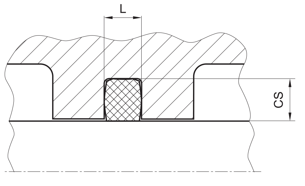
for inside diameters of 25 mm or more, and dependant on the radial cross section (cs), the seal can be snapped into the housing.
| Ød | type of installation |
| ≤ 6•cs | open mounting space required |
| > 6•cs …..≤ 10•cs | snap mounting with tool |
| > 10•cs | snap mounting by hand |
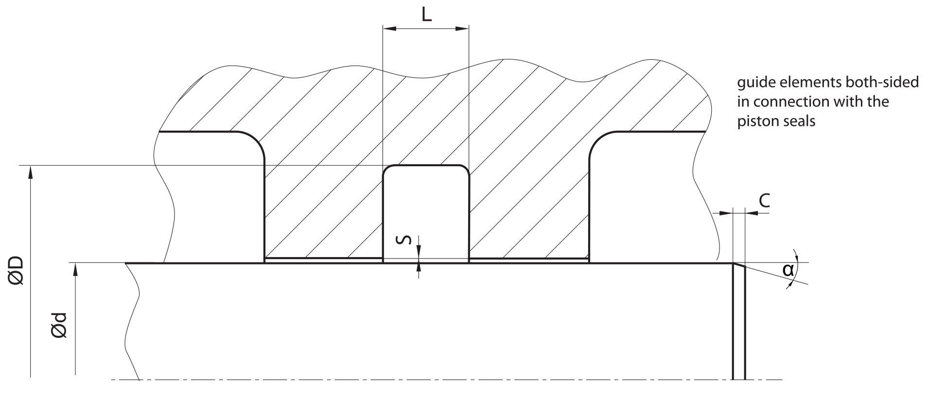
recommended mounting space:
recommended guide tolerance D1:
in most cases the guiding elements are integrated in the piston seal system on both sides. if not use below recommendations for D1 (=inside diameter of the guiding elements):
| d f8 [mm] |
p ≤ 100 [bar] |
100 < p ≤ 200 [bar] |
p > 200 [bar] |
| ≤ 100 | H10 | H8 | H8 |
| > 100 ≤ 200 | H10 | H8 | H7 |
| >200 | H9 | H8 | H7 |
insertion chamfer:
in order to avoid damage to the rod seal during installation, the piston rod is to be chamfered and rounded as shown in the “recommended mounting space” drawing. the size of chamfer depends on the seal type and profile width.
| cs (mm) | c (mm) | |
| α = 15⁰ … 20⁰ | α = 20⁰ … 30⁰ | |
| 4 | 3.5 | 2 |
| 5 | 4 | 2.5 |
| 6 | 4.5 | 3 |
| 7.5 | 5 | 4 |
| 10 | 6 | 5 |
| 12.5 | 8.5 | 6.5 |
| 15 | 10 | 7.5 |
| 20 | 13 | 10 |
seal & housing recommendations
please note that we are able to produce those profiles to your specific need or any non standard housing. for detail measurements, please see Jet seal pars catalog…
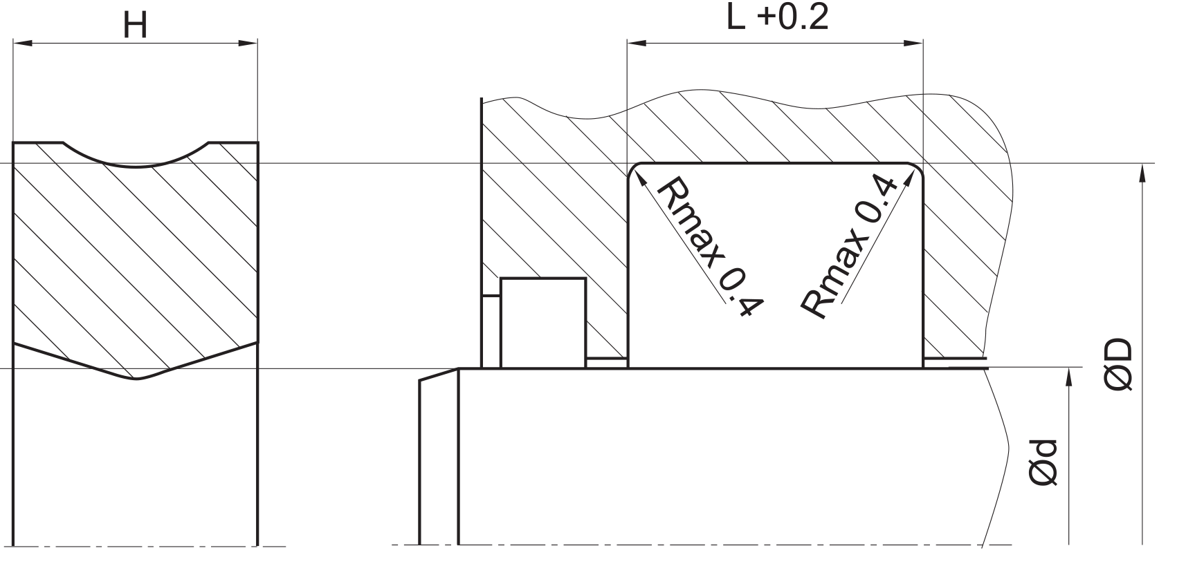
we recommed the following values for cross sections and housing heights in accordance to the diameter range:
| Ød [mm] | cs = (ØD – Ød)/2 [mm] | L [mm] |
| 5 – 9.9 | 2.5 | 4 |
| 10 – 24.9 | 3 | 4.5 |
| 25 – 49.9 | 4 | 5.5 |
| 50 – 99.9 | 5 | 6.5 |
| 100 – 149.9 | 7.5 | 9.5 |
| 150 – 299.9 | 10 | 12.5 |
| 300 – 499.9 | 12.5 | 15 |
| 500 – 700 | 15 | 17.5 |
| >700 | 20 | 22 |
fitted:
don’t hesitate to contact our technical department for further information or for special requirements (temperature, speed etc.), so that suitable materi- als and/or designs can be recommended.